Control apparatus and control method of internal combustion engine

Inactive Publication Date: 2009-11-26
TOYOTA JIDOSHA KK
View PDF5 Cites 50 Cited by
  • Summary
  • Abstract
  • Description
  • Claims
  • Application Information

AI Technical Summary

Benefits of technology

[0006]This invention thus provides a control apparatus of an internal combustion engine, which is capable of promp

Problems solved by technology

In the first aspect described above, the fuel injection control portion may prohibit control that increases and

Method used


Image

  • Control apparatus and control method of internal combustion engine
  • Control apparatus and control method of internal combustion engine
  • Control apparatus and control method of internal combustion engine

Examples


Example

[0027]In the following description and the accompanying drawings, the present invention will be described in more detail in terms of example embodiments. First the overall structure of a system to which the control apparatus of an internal combustion engine according to an example embodiment of the invention has been applied will be described.

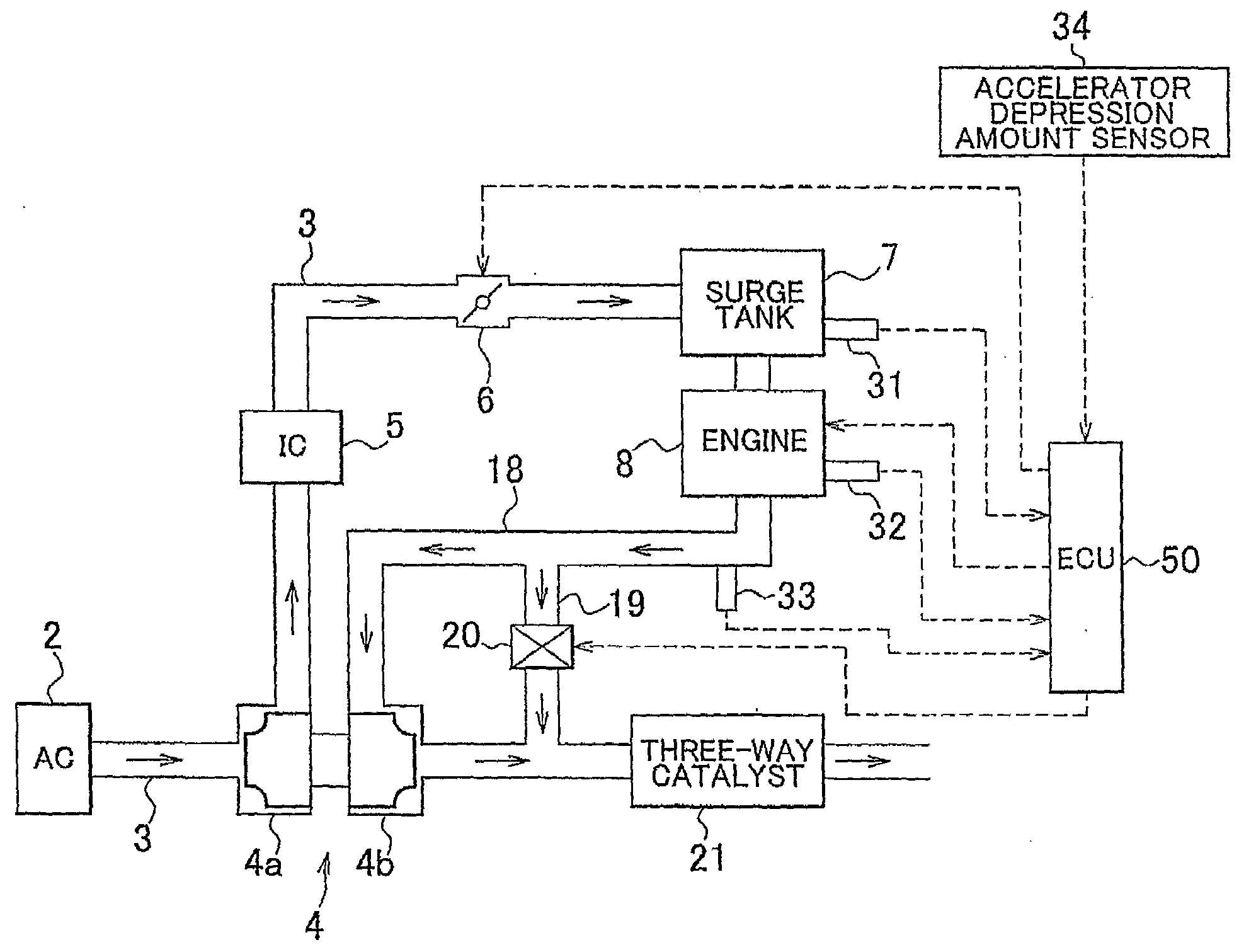
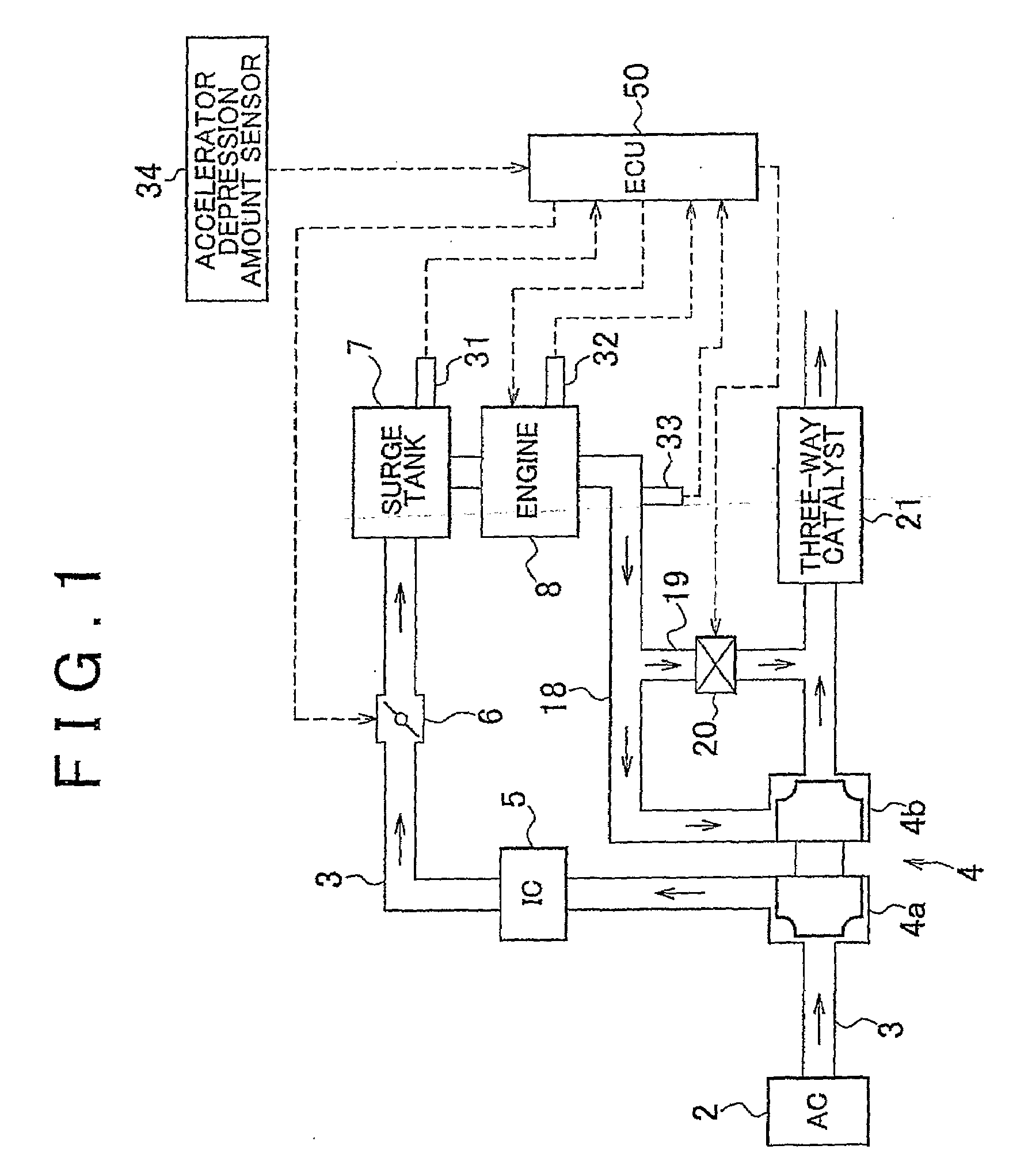
[0028]FIG. 1 is a schematic diagram of the structure of a vehicle to which a control apparatus of an internal combustion engine according to this example embodiment has been applied. In the drawing, the solid arrows indicate the flow of gas and the broken arrows indicate signal input and output.

[0029]The vehicle is mainly provided with an air cleaner (AC) 2, an intake passage 3, a turbocharger 4, an intercooler (IC) 5, a throttle valve 6, a surge tank 7, an engine (i.e., an internal combustion engine) 8, an exhaust passage 18, a bypass passage 19, a wastegate valve 20, a three-way catalyst 21, an intake air pressure sensor 31, a coolant tempera...


PUM


Abstract

A control apparatus of an internal combustion engine performs control to warm up a catalyst. More specifically, the control apparatus keeps a wastegate valve open when the temperature of the catalyst is less than a predetermined temperature and closes the wastegate valve when the temperature of the catalyst becomes equal to or greater than the predetermined temperature. The control apparatus executes control to increase and decrease the fuel injection quantity such that the internal combustion engine alternately switches between lean burn and rich burn when the wastegate valve is closed. Accordingly, rich gas and lean gas can be reliably mixed in the catalyst, and CO can be reliably combusted in the catalyst. Therefore, the catalyst can be promptly warmed up while CO, HC, and the like can be appropriately suppressed from flowing through the catalyst.

Description

BACKGROUND OF THE INVENTION[0001]1. Field of the Invention[0002]The invention relates to a control apparatus and a control method of an internal combustion engine, which performs control to promptly warm up a catalyst.[0003]2. Description of the Related Art[0004]Catalyst warm-up control that raises the temperature of an exhaust gas control catalyst to activation temperature is performed at times such as after startup of an internal combustion engine. For example, Japanese Patent Application Publication No. 9-88663 (JP-A-9-88663) describes technology for promptly warming up a catalyst by increasing and decreasing the fuel injection quantity to supply the catalyst with oxygen from lean burn and a combustible component (such as CO (carbon monoxide)) from rich burn. Executing this kind of control promotes the oxidation reaction of the CO in the catalyst, and the heat generated by this oxidation reaction promotes catalyst warm-up. Also, Japanese Patent Application Publication No. 2001-10...

Claims


Application Information

Patent Timeline
IPC IPC(8): F02D43/00F02D23/00
CPCF02B37/18F02D41/0007Y02T10/26Y02T10/144F02D41/0255Y02T10/12
Inventor TANAKA, TOSHIHIKO
Owner TOYOTA JIDOSHA KK
Why Eureka
Try Eureka