Parallel sample loading and injection device for multichannel microfluidic devices

a microfluidic device and sample technology, applied in the direction of fluid pressure measurement, liquid/fluent solid measurement, peptide measurement, etc., can solve the problems of difficult to achieve, less developed methods for moving small quantities of samples from a sample vial or holder onto a chip or directly to an analytical device without evaporation or dilution, etc., and achieves high surface area

Inactive Publication Date: 2005-09-06
NORTHEASTERN UNIV
View PDF7 Cites 46 Cited by
  • Summary
  • Abstract
  • Description
  • Claims
  • Application Information

AI Technical Summary

Benefits of technology

[0012]Samples can be introduced into a channel on a microfluidic device by the sample loading and injection device of the invention by a variety of methods, e.g., by pressure, electrokinetic injection, or other technique, and an electrical current and / or pressure drop can then be applied to cause the sample components to migrate along the channel. The channels may function only for fluid transfer, e.g., to a mass spectrometer, or the channels can serve as environments for various types of sample manipulations, e.g., for micropreparative or analytical operations, such as capillary electrophoresis (CE), chromatography or the polymerase chain reaction (PCR), or for carrying out any type of sample chemistry. The channels may be filled with membrane or packing material to effectuate preconcentration or enrichment of samples or for other treatment steps, such as desalting. Furthermore, other modification of sample components, e.g., by enzymes that are covalently bound to the walls of a channel or are free in a channel, are possible. Packing material may be bound to the walls of the channels or may include other components, such as magnetic particles, so that when a magnetic field is applied, the magnetic particles retain the packing material in place. The magnetic particles can also be used for efficient mixing of fluids inside the channels, using an external magnetic field. A micromachined filter or other stationary structure may also be employed to hold packing material in place. Alternatively, stationary structures can be micromachined, cast or otherwise formed in the surface of a channel to provide a high surface area which can substitute for packing material.
[0013]A sample can be introduced into a channel in a short starting zone or can fill the whole channel completely. Filling only a small part of the channel with the sample is preferable when an on-chip separation of sample components is to be carried out, such as electrophoresis or chromatography. Filling the whole channel with the sample may be advantageous in cases when off-chip analysis requires extended sample outflow, such as sample introduction / electrospray ionization for structure analysis by mass spectrometry.

Problems solved by technology

However, methods for moving small quantities of samples from a sample vial or holder onto a chip or directly to an analytical device without either evaporation or dilution are less well developed.
One important issue for the further development of microfluidic devices is that sample introduction into a device and subsequent injection of a sample aliquot into, e.g., a separation channel or reaction compartment on the device must be carried out in a reliable, accurate and convenient manner.
This is very difficult to accomplish when multiple channels on one microfluidic device are used.

Method used


Image

  • Parallel sample loading and injection device for multichannel microfluidic devices
  • Parallel sample loading and injection device for multichannel microfluidic devices
  • Parallel sample loading and injection device for multichannel microfluidic devices

Examples


Embodiment Construction

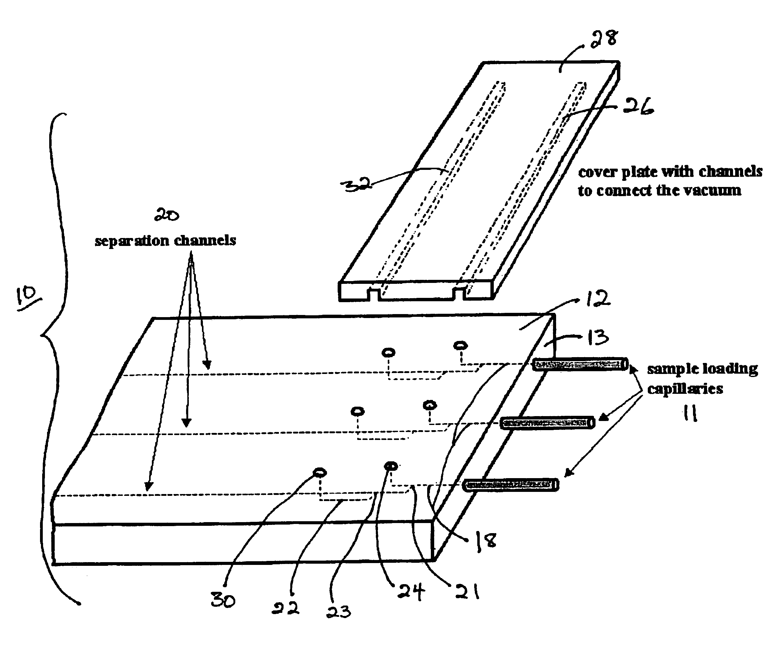
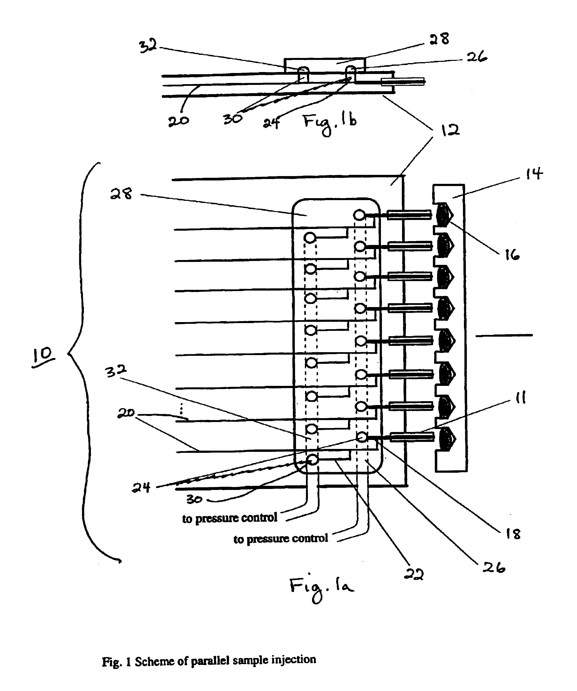
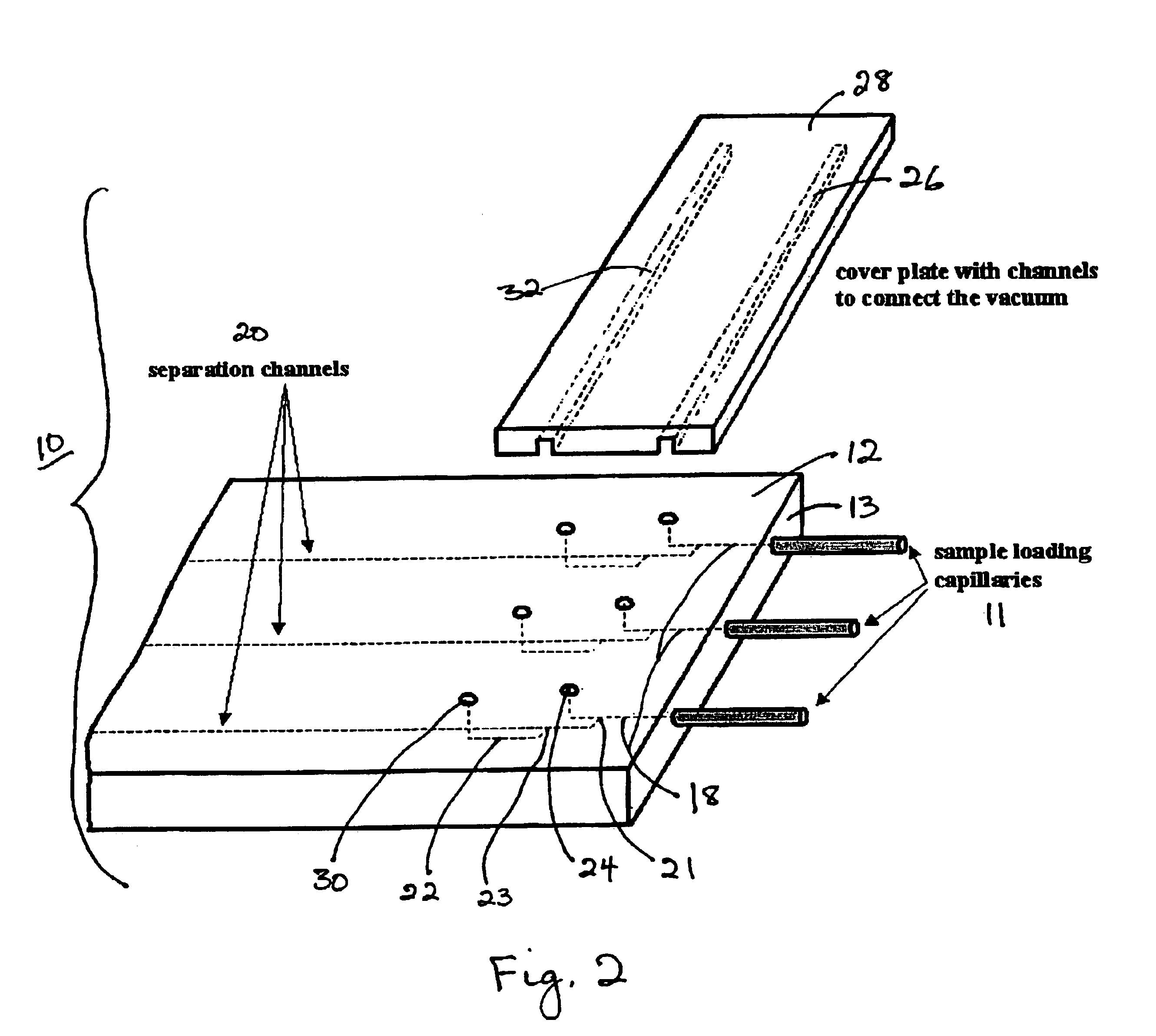
[0022]The parallel sample load and injection device of the invention allows for a simple automated way of transferring samples from a standard, e.g., 96-well, microtiter plate into a microfluidic device and for the simultaneous or subsequent injection of samples into multiple channels on the device.

[0023]Referring to FIGS. 1a-3, a sample load and injection device (10) includes parallel sample introduction capillaries (11) that are attached to a microfluidic device (12) into which the sample load and injection device of the invention is integrated. The spacing between these capillaries is compatible with the spacing of the wells in standard microtiter plates (14). As indicated in FIG. 3, individual sample introduction capillaries (11) may contain packing material (15) for sample pretreatment.

[0024]Sample solutions in individual wells (16) are transferred through introduction capillaries (11) into introduction channels (18) in the sample load and injection device. Each of the sample i...


PUM

PropertyMeasurementUnit
pressureaaaaaaaaaa
electric fieldaaaaaaaaaa
internal diameteraaaaaaaaaa

Abstract

A sample load and injection device (10) includes sample introduction capillaries (11) attached to a microfluidic device (12). Sample introduction capillaries (11) are connected to sample introduction channels (18). Sample introduction capillaries (18) are connected to separation channels (20) at connection points (21). At a defined distance along the separation channels (20), auxilliary channels (23) originate at connection points (24). The sample load and injection device includes cover plate (28) which has connecting channels (26, 32). Connecting channel (26) is associated with ends (24) of sample introduction channels (18). Connecting channel (32) is associated with ends (20).

Description

CROSS REFERENCE TO RELATED APPLICATIONS[0001]This application claims the priority of U.S. Provisional Application No. 60 / 176,183 filed Jan. 18, 2000, and of PCT International Patent Application No. PCT / US00 / 09480 filed Apr. 10, 2000, the whole of which are hereby incorporated by reference herein.STATEMENT REGARDING FEDERALLY SPONSORED RESEARCH OR DEVELOPMENT[0002]Part of the work leading to this invention was carried out with United States Government support provided under a grant from the National Institutes of Health, Grant No. NIH (GM15847). Therefore, the U.S. Government has certain rights in this invention.BACKGROUND OF THE INVENTION[0003]Recent developments in microfabrication techniques have permitted the integration of microminiature tools for biochemical analysis within a tiny microfluidic device. Microfluidic devices have been successfully demonstrated as useful for a wide variety of separation techniques as well as for sample pretreatment and / or manipulation methods. Comp...

Claims


Application Information

Patent Timeline
Patent Type & Authority Patents(United States)
IPC IPC(8): B01L3/00G01N27/447
CPCB01L3/502715G01N27/44743G01N27/44791B01L3/5025B01L2200/027B01L2400/0415B01L2400/049
Inventor FORET, FRANTISEKREJTAR, THOMASZHANG, BAILINKARGER, BARRY L.
Owner NORTHEASTERN UNIV
Why Eureka
Try Eureka