Carbon nanotube-containing structures, methods of making, and processes using same

a carbon nanotube and structure technology, applied in the direction of catalyst activation/preparation, solid-state diffusion coating, metal/metal-oxide/metal-hydroxide catalyst, etc., can solve the problems of cracking into powders or particles, unable to predict the synthesis of these materials in novel combinations with varying substrates, etc., and achieves enhanced reaction rate, high surface van der waal force and hydrophobic properties. , the effect of improving the performan

Inactive Publication Date: 2006-03-14
BATTELLE MEMORIAL INST
View PDF13 Cites 115 Cited by
  • Summary
  • Abstract
  • Description
  • Claims
  • Application Information

AI Technical Summary

Benefits of technology

[0014]The invention also provides processes of using carbon nanotube-containing structures. Preferably, any of the carbon nanotube-containing structures described herein can be used in processes or devices including: catalysis, adsorption, ion exchange, separation of chemical components, filtration, storage of gases (for example, hydrogen or carbon dioxide), distillation (including reactive distillation), a support structure for chemical, including biological, sensors, a support structure to immobilize proteins for bioprocessing, and a component in a heat exchanger. Features of carbon nanotube-containing structures that make these structures particularly advantageous include: high surface area, excellent thermal conductivity, capillary force for enhanced condensation, and good attractive force for certain organic species.
[0016]Similarly, the invention provides a method of separating a chemical component from a mixture of components. “Mixture” also includes solutions, and “separating” means changing the concentration of at least one component relative to the concentration of at least one other component in the mixture and preferably changes the concentration of at least one component by at least 50% (more preferably at least 95%) relative to at least one other component, for example, reducing the concentration of a 2M feed stream to 1M or less. Particular types of separations include filtration, selective adsorption, distillation and ion exchange. Filtering can be accomplished, for example, by passing a mixture having at least two phases through a porous carbon nanotube-containing structure where at least one of the phases gets physically caught in the structure. A carbon nanotube-containing structure with surface-exposed carbon nanotubes can function efficiently for the separation of some organics because the nanotubes can be hydrophobic while organics can be adsorbed quite well. For ion exchange it is desirable to coat the surface with an ion exchange agent.
[0017]The preparation of porous materials, such as foams, coated with carbon nanotubes and a high-surface area metal oxide coating, can be difficult. The locally aligned nanotubes exhibit high surface Van der Waal forces and hydrophobic properties. Conventional wash coating of metal oxides using aqueous based solution often results in a non-uniform coating or poor adhesion onto the nanotubes. We have developed treatment methods to modify the surface properties of the nanotubes, making this new class of materials possible for a variety of important industrial applications such as engineered catalyst structures. The invention has particular utility in the chemical (including biological), fossil fuel, automotive, and environmental industries. For example, we have fabricated a carbon nanotube-based engineered catalyst and have demonstrated its performance for Fisher-Tropsch reaction in a microchannel reactor. Under operating conditions typical of microchannel reactors with minimal heat and mass transfer limitations, it was found that the integrated nanotube structure has further improved the performance, as indicated by enhanced reaction rate and improved product selectivity. This concept can also be applied toward conventional reactors, which operate under severe heat and mass transfer inhibitions with catalyst performance far less than that predicted from the intrinsic kinetics.
[0018]Various embodiments of the present invention can offer numerous advantages, including: creating larger pores through which flow occurs, improved heat transport, controlling the direction of heat transport, enhanced surface area, excellent thermal stability, excellent thermal conductivity, reduced mass transfer limitations, utility in microreactors, ready adaptability in fixed-bed type reactors, and increased loading levels of catalyst or other active materials.
[0019]The surface area enhancement that arises from these nanoscale fibers can greatly increase the active site density (for example, catalyst site density) within a fixed reactor volume. The potential to create larger pore size naturally generated from the interstices between carbon nanotubes can be beneficial for processes involving liquid phases, since the transport of gas phase molecules through a liquid phase inside the pores is often the rate-limiting step which not only hinders the rate of a process, but may also adversely affect product selectivity of a chemical reaction.

Problems solved by technology

However, the reactivities of these materials in novel combinations and the synthesis of these materials in novel combinations with varying substrates, coatings, etc., cannot be predicted.
It appears from the paper of Xie et al. that drying of the mesoporous silica results in cracking into powders or particles with surface dimensions of a few square millimeters.

Method used


Image

  • Carbon nanotube-containing structures, methods of making, and processes using same
  • Carbon nanotube-containing structures, methods of making, and processes using same
  • Carbon nanotube-containing structures, methods of making, and processes using same

Examples


examples

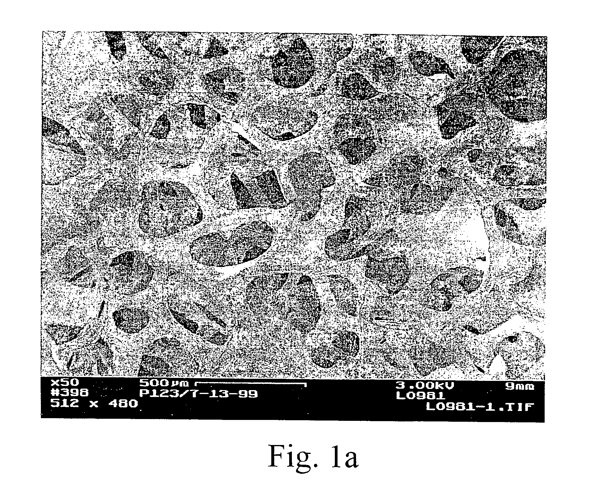
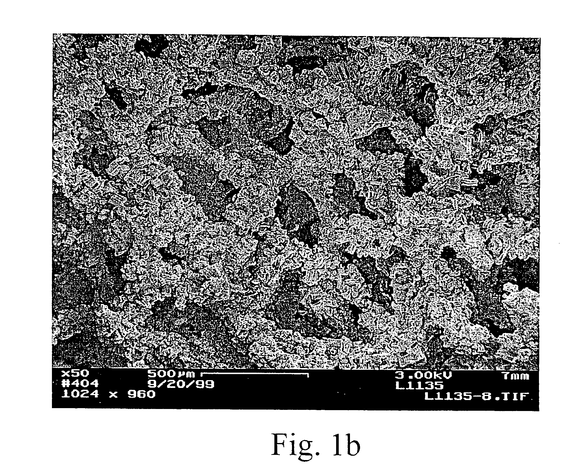
[0064]Layered, aligned carbon nanotubes on metal and ceramic foams were prepared and characterized. The figures show various SEM views of various coated and uncoated foams. FIG. 1a is an SEM view of a FeCrAlY alloy foam. FIG. 1b shows the same type of foam after depositing carbon nanotubes. From the photomicrograph, one can see chunks of aligned nanotubes coating the foam while leaving large pores through the structure. Higher magnification views are shown in FIGS. 1c and 1d. In FIG. 1d the carbon nanotubes appear curved and wavy (kinked). Thus, the nanotubes have a local alignment (see, e.g., FIGS. 1b, 1c) but a jumbled, high surface area orientation at a very high magnification. Thus showing a preferred arrangement in which nanotube alignment is observed at 2000× magnification while substantial kinkiness is observed at 20,000×. The interior of a nanotube-coated metal foam support was viewed by SEM of a cross-sectional cut (not shown) demonstrated that the technique was effective t...


PUM

PropertyMeasurementUnit
sizeaaaaaaaaaa
diameteraaaaaaaaaa
diameteraaaaaaaaaa

Abstract

Carbon nanotube structures are disclosed in which nanotubes are disposed over a porous support such as a foam, felt, mesh, or membrane. Techniques of making these structures are also disclosed. In some of these techniques, a support is pretreated with a templated surfactant composition to assist with the formation of a nanotube layer.

Description

RELATED APPLICATION[0001]This application is a divisional of U.S. patent application Ser. No. 10 / 036,332, now U.S. Pat. No. 6,824,684 was a continuation-in-part of U.S. patent application Ser. No. 10 / 032,207, filed Dec. 21, 2001, now U.S. Pat. No. 6,713,519.STATEMENT OF GOVERNMENT RIGHTS[0002]This invention was made with Government support under contract DE-AC0676RLO 1830 awarded by the U.S. Department of Energy. The Government has certain rights in this invention.FIELD OF THE INVENTION[0003]The present invention relates to structures containing carbon nanotubes, methods of making structures containing carbon nanotubes on porous substrates, and processes using carbon nanotube-containing structures.INTRODUCTION[0004]Carbon nanotubes, graphite-like sheets rolled up in coaxial cylinders, have been studied intensively since their discovery in 1991. Nanotubes were found in single sheet wall or multi-wall form with diameters of 3-100 nm and up to 200 μm long. These new carbon materials ha...

Claims


Application Information

Patent Timeline
Patent Type & Authority Patents(United States)
IPC IPC(8): B01D15/00B01J19/00B01J20/20B01J20/32B01J21/18B01J23/889B01J35/04B01J35/10B01J37/02B01J37/03C01B31/02C04B41/52C04B41/89C10G2/00C23C8/02C23C8/80C23C26/00C23C28/00F28F21/02
CPCB01D69/141B01J19/0093B01J20/20B01J20/32B01J21/18B01J23/8896B01J35/04B01J37/0225B01J37/0244B82Y30/00B82Y40/00C01B31/0233C04B41/52C04B41/89C10G2/33C10G2/332C23C8/02C23C8/80C23C26/00F28F21/02Y10T428/30B01J35/10B01J37/0238B01J37/033F28F2260/02Y02C10/08F28F2255/20Y10S977/843B01D2323/283B01J20/3204B01J20/3219B01J20/324B01J20/3289B01J20/3291B01J20/205C01B32/162Y02C20/40Y02P20/10B01D69/108
Inventor WANG, YONGCHIN, YA-HUEIGAO, YUFEIAARDAHL, CHRISTOPHER L.STEWART, TERRI L.
Owner BATTELLE MEMORIAL INST
Why Eureka
Try Eureka