
Gradient porous implant

Active Publication Date: 2007-06-28
HOWMEDICA OSTEONICS CORP
View PDF31 Cites 250 Cited by
  • Summary
  • Abstract
  • Description
  • Claims
  • Application Information

AI Technical Summary

Benefits of technology

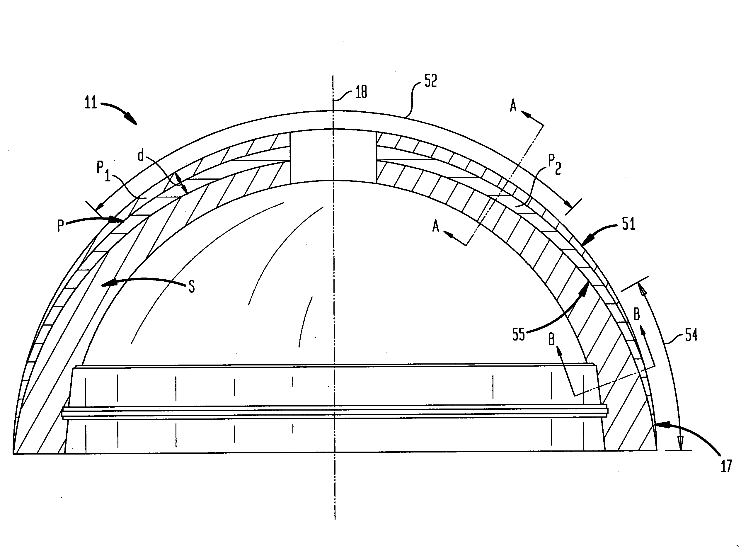
[0030] In another aspect, the invention modifies the thickness of the porous metal foam or foam-like structure in different regions of the structure in order to establish a thickness profile that optimizes various mechanical and biological requirements of the implants performance. These requirements include increasing the thickness of the structure adjacent cancellous bone to allow deeper bone ingrowth in the higher growth cancellous bone region and to allow the implant to be less rigid and more resilient in order to better match the cancellous bone characteristics, and if desired, better transmit the joint load against the bone. Conversely, the thickness of the porous structure is decreased or the thickness of the solid structure is increased adjacent peripheral denser bone in response to typically higher insertion loads imposed in the region. This increase in rigidity around the rim maximizes the cups dimensional stability which is required for certain hard on hard bearings.
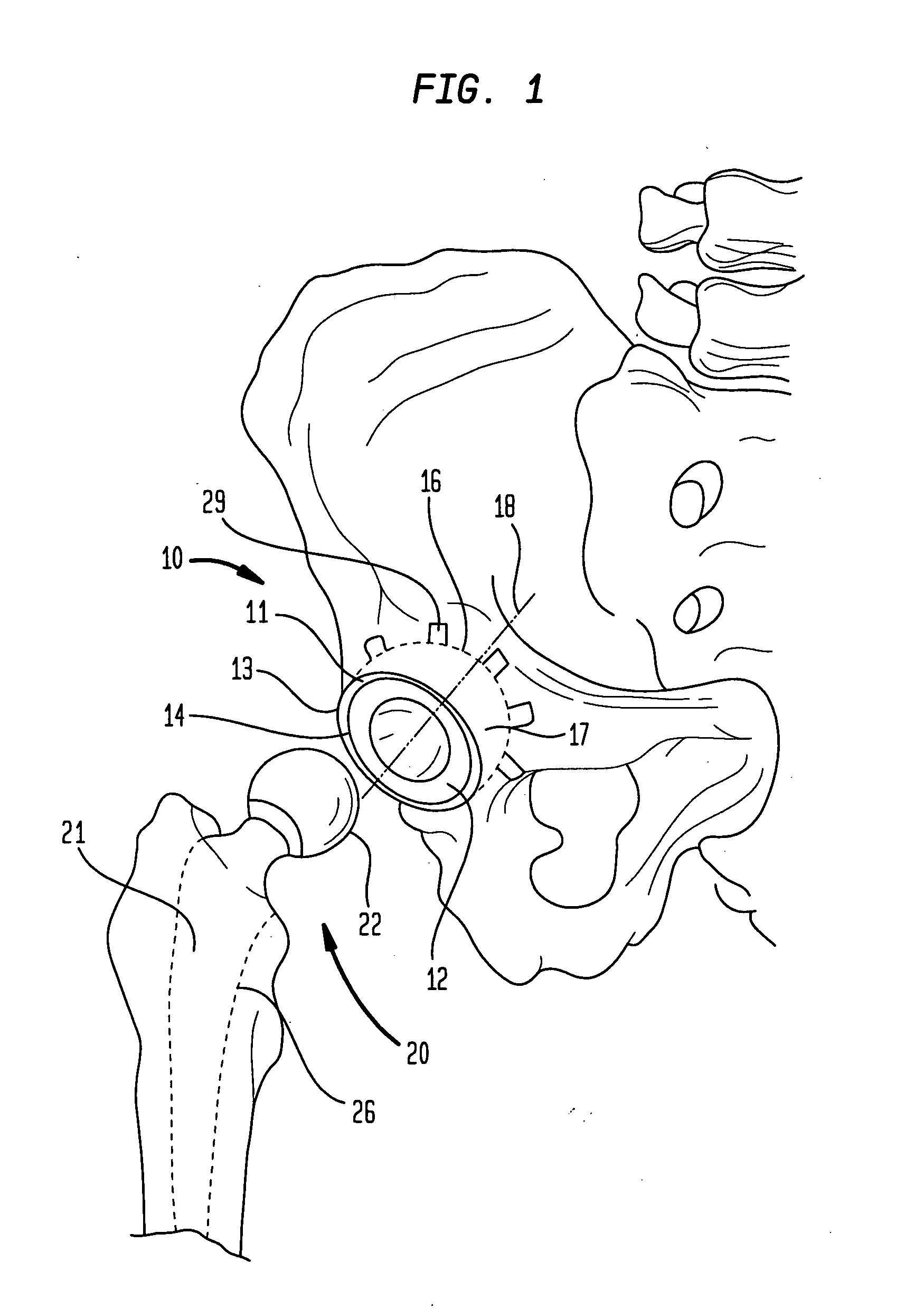
[0031] In another aspect, the invention is an acetabular cup implant with an outer, generally hemispherical, porous metal foam or foam-like layer for contacting bone. The outer layer has a first porosity and thickness in the equatorial or rim region that is typically in contact with dense bone of the acetabulum and a second porosity and thickness in the polar or dome region that is generally in contact with the cancellous bone of the acetabulum. The second thickness is greater than the first thickness to allow deeper bone ingrowth and to allow the dome to be less rigid and more resilient in order to better match the cancellous bone characteristics. If the dome region is more porous or has other pore characteristics that decrease the modulus of elasticity in the dome region, such as thinner struts in the cancellated structure, this further augments the desired decrease in rigidity and increase in resiliency of the dome region.
[0032] In accordance with an aspect, the invention is an acetabular cup implant with an outer, generally hemispherical, porous metal foam or foam-like layer for contacting bone. The outer layer surface has a first porosity gradient in the equatorial or rim region and a first surface porosity in the equatorial or rim region that is typically in contact with denser bone of the acetabulum. The outer surface layer also has a second porosity gradient in the polar or dome region and a second surface porosity in the polar or dome region that is generally in contact with the cancellous or less dense subchondral bone of the acetabulum. The second surface porosity is greater than the first surface porosity to better allow cancellous bone ingrowth and to allow the dome to be less rigid and more resilient in order to better match the cancellous bone characteristics. The porosity in each region decreases with depth from each respective surface porosity to a lower porosity that better matches the strength and modulus of elasticity of the shell substrate.
[0047] In another aspect of the invention, the process of thickening the green metal foam by applying a solution of a binder onto the green foam, applying a metal powder having a pre-determined particle size, and sintering the foam described in the '981 application, is modified to selectively sinter varying amounts of metal powder to different regions of the green metal foam to vary the pore characteristics, such as porosity. Variations in the amount of metal powder sintered to the foam can be created by varying the amount and location of binder applied, varying the amount and location of metal powder applied, and by selectively removing binder or metal powder prior to sintering. As described in the '981 application, the cycle of applying the binder, applying the metal powder and sintering can be repeated. By applying and sintering the metal powder to selected regions during latter cycles, the porosity, for instance, can be reduced in the selected regions.

Problems solved by technology

The use of orthopedic implants is the result of deterioration of human bone structure, usually because of various degenerative diseases, such as osteoarthritis.
A breakdown of a permanently installed implant leads to pain, limitation on the range of motion, and may require a replacement of the implant.
It is especially important since installation of an orthopedic implant often involves an extensive and difficult medical procedure, and therefore replacement of the installed implant is highly undesirable.
Thus, one of the challenges is to provide metallic orthopedic implants having porous metallic bone interfaces with appropriate pore sizes, high pore connectivity and high porosity.
An additional challenge is that implants with an open porous structure are generally mechanically weaker than those with a denser, less porous, structure.
Such methods do not provide a high porosity (typically they are below 50%), high cell interconnectivity or optimum control of pore characteristics.
The porosity of the foam is over 90%, but it is produced by a method that is in many respects not suitable for producing foams of biocompatible metals typically used in making implants, such as tantalum or titanium.
Purportedly, variation in the angle of incidence of the particles in the layer by layer deposition of the particles by a flame-plasma process results in a larger pore size and porosity at the surface.
The example provided does not disclose a method for creating a gradient porosity implant.
Because the cup is initially an interference fit in the acetabular socket, the cup may have large radial loads in the rim region once installed that can distort the hemisphere in that region inward and create excess bearing stress and even binding in the equatorial region of the bearing surface.

Method used


Image

  • Gradient porous implant
  • Gradient porous implant
  • Gradient porous implant

Examples


Embodiment Construction

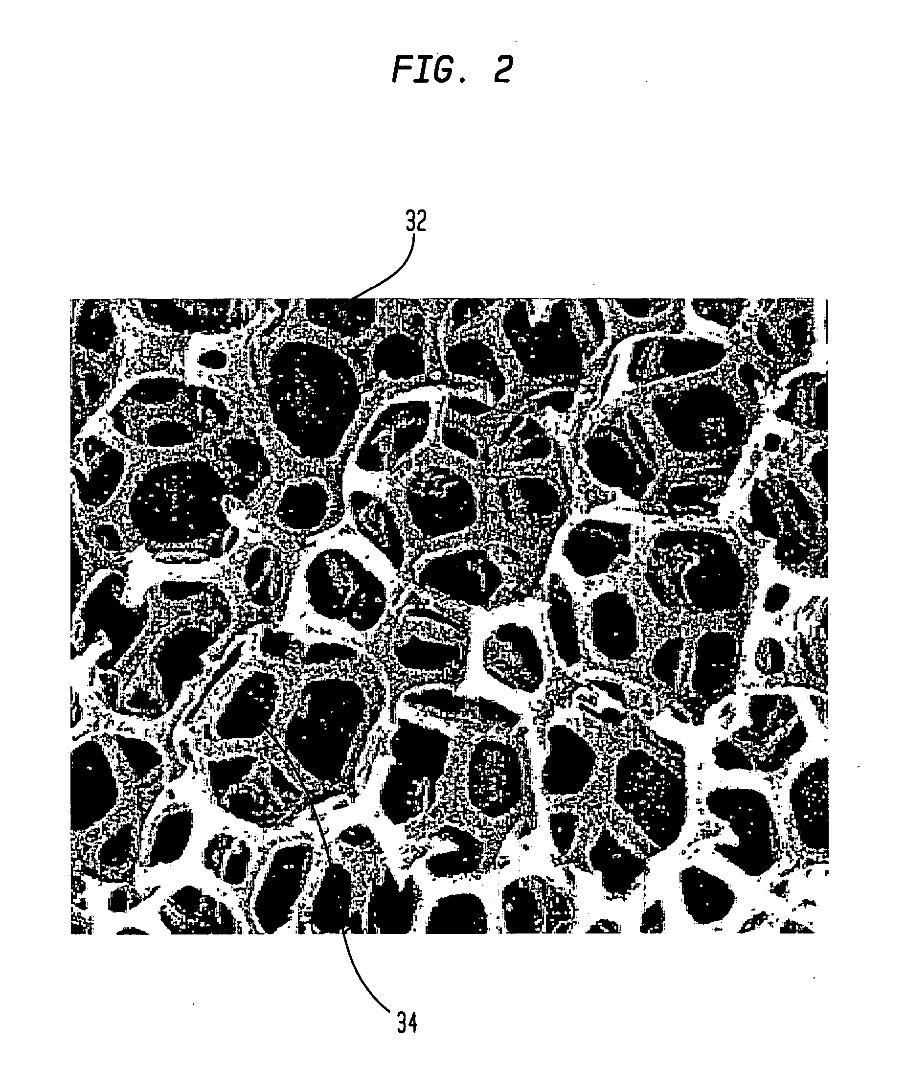
[0067] In accordance with one embodiment, the invention provides a porous metallic foam or foam-like structure suitable for medical device application, especially for orthopedic implants with gradient pore characteristics. The porous metal foam structure has pores defined by metal struts or webs wherein the porous structure has directionally controlled pore characteristics. The pore characteristics controlled include one or more of the metal foam porosity, pore size, pore shape, pore size distribution and web thickness. The pore characteristics may vary in one or more directions throughout the structure. It will be understood that although, for reasons of clarity, the primary varying pore characteristics discussed will be the porosity and pore size, a person of skill in the art will understand the applicability of the various apparatus and methods disclosed to other pore characteristics.

[0068] Preferably the pore characteristics are selectively modified to adapt the porous metal fo...


PUM

PropertyMeasurementUnit
Pore sizeaaaaaaaaaa
Pore sizeaaaaaaaaaa
Pore sizeaaaaaaaaaa

Abstract

An implantable medical device includes a porous metal foam or foam-like structure having pores defined by metal struts or webs wherein the porous structure has directionally controlled pore characteristics. The pore characteristics controlled include one or more of the metal structure porosity, pore size, pore shape, pore size distribution and strut thickness. The pore characteristics may vary in one or more directions throughout the structure. Preferably the pore characteristics are controlled to match the porous metal structure to various mechanical and biological requirements of different regions of the structure in order to optimize aspects of the implants performance and may vary not only over the surface of the porous structure but through the depth of the porous structure. The thickness of the porous metal structure may also be modified to establish a thickness profile that optimizes mechanical and biological requirements of the implants performance. Acetabular cup embodiments of the invention are described. Various methods of manufacturing implants having directionally controlled pore characteristics are described.

Description

BACKGROUND OF THE INVENTION [0001] The present invention relates to implantable medical devices, and in particular to metallic porous structures for implantable medical devices including orthopedic implants, especially acetabular cup implants, methods of forming such metallic porous layers for implants, and methods of producing such devices. [0002] The use of orthopedic implants is the result of deterioration of human bone structure, usually because of various degenerative diseases, such as osteoarthritis. In recent years, a variety of implantable orthopedic devices have been developed. Typically, the failed bone structure is replaced with an orthopedic implant that mimics, as closely as possible, the structure of the natural bone and performs its functions. [0003] Orthopedic implants are constructed from materials that are stable in biological environments and withstand physical stress with minimal or controlled deformation. Such materials must possess strength, resistance to corro...

Claims


Application Information

Patent Timeline
IPC IPC(8): A61F2/32
CPCA61B17/86A61F2/30767A61F2/3094A61F2/32A61F2/34A61F2/36A61F2/3662A61F2/367A61F2/3672A61F2/3676A61F2002/30011A61F2002/30322A61F2002/30324A61F2002/30769A61F2002/30822A61F2002/30838A61F2002/3092A61F2002/30929A61F2002/30968A61F2002/3403A61F2002/3611A61F2002/3631A61F2002/368A61F2250/0023A61F2250/0026A61F2250/0036A61F2310/00011A61F2310/00017A61F2310/00023A61F2310/00029A61F2310/00095A61F2310/00131A61F2310/00179A61F2310/00401A61F2310/00407A61F2310/00413A61F2310/00491A61F2310/00544B22F3/1137B22F3/1146B22F2998/10B22F2999/00C23C26/00C23C28/00B22F2207/13C23C28/026C23C28/028B33Y80/00
Inventor DONG, NICHOLAS NAI GUANGWANG, AIGUOJONES, ERICPLASKON, GREGORY E.
Owner HOWMEDICA OSTEONICS CORP
Learn More