Method and apparatus for the measurement and control of both the inside and outside surface temperature of thermoplastic preforms during stretch blow molding operations

US20050146065A1Active Publication Date: 2005-07-07PRESSCO IP

Image

  • Method and apparatus for the measurement and control of both the inside and outside surface temperature of thermoplastic preforms during stretch blow molding operations
  • Method and apparatus for the measurement and control of both the inside and outside surface temperature of thermoplastic preforms during stretch blow molding operations
  • Method and apparatus for the measurement and control of both the inside and outside surface temperature of thermoplastic preforms during stretch blow molding operations

Examples


Embodiment Construction

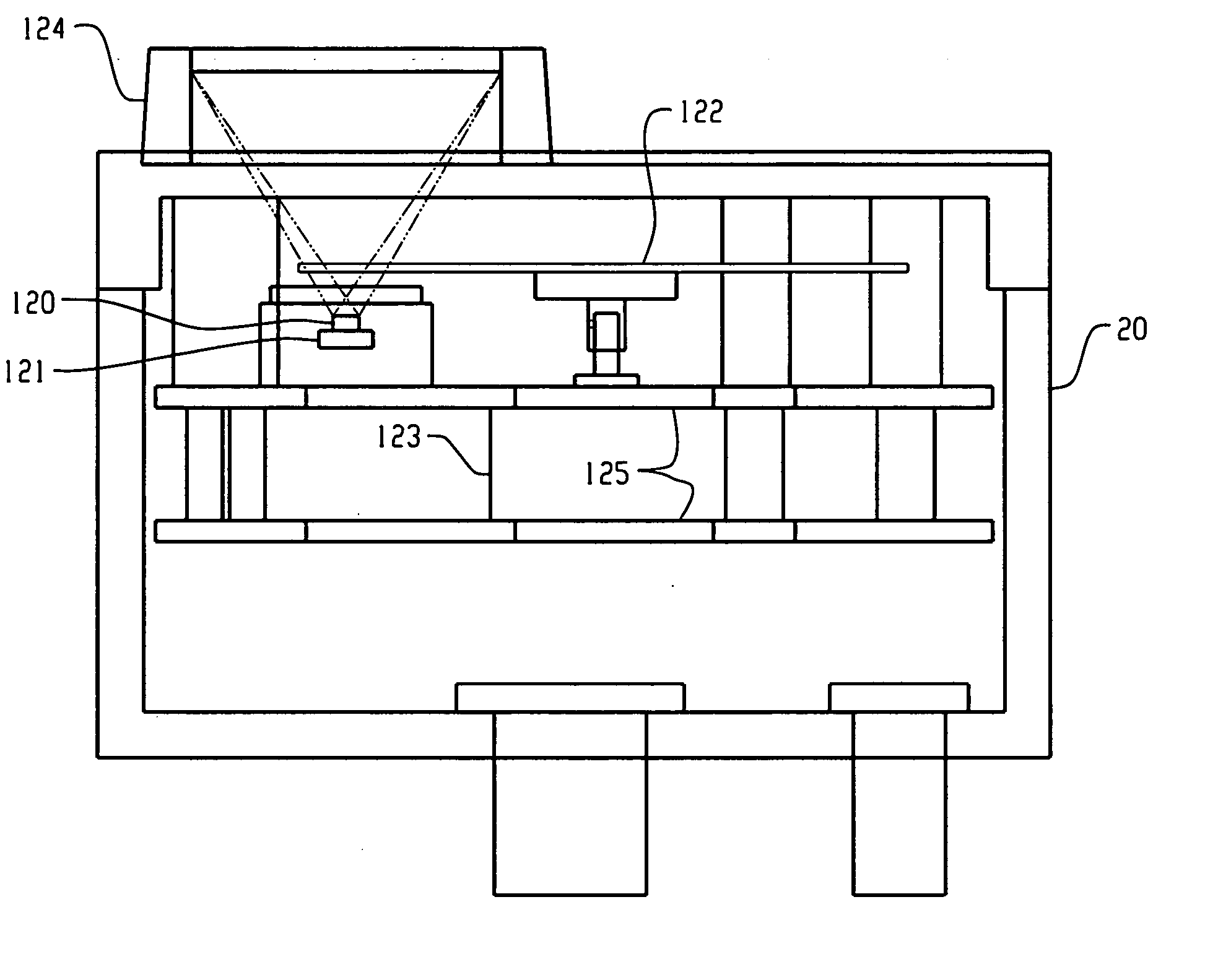
[0027] An objective of this invention is to provide a blow molding system having an improved thermal conditioning section with improved temperature measurement and control features. The temperature measurement and control features enable the system to directly monitor one or both of the outside and inside surface temperatures of preforms at different stages of transport throughout the thermal conditioning section of the system. That is, the present invention implements a methodology for the direct and precise measurement of individual preforms and selected sub-portions thereof. This advancement in the art was not heretofore known and provides significant advantages in the blow molding field.

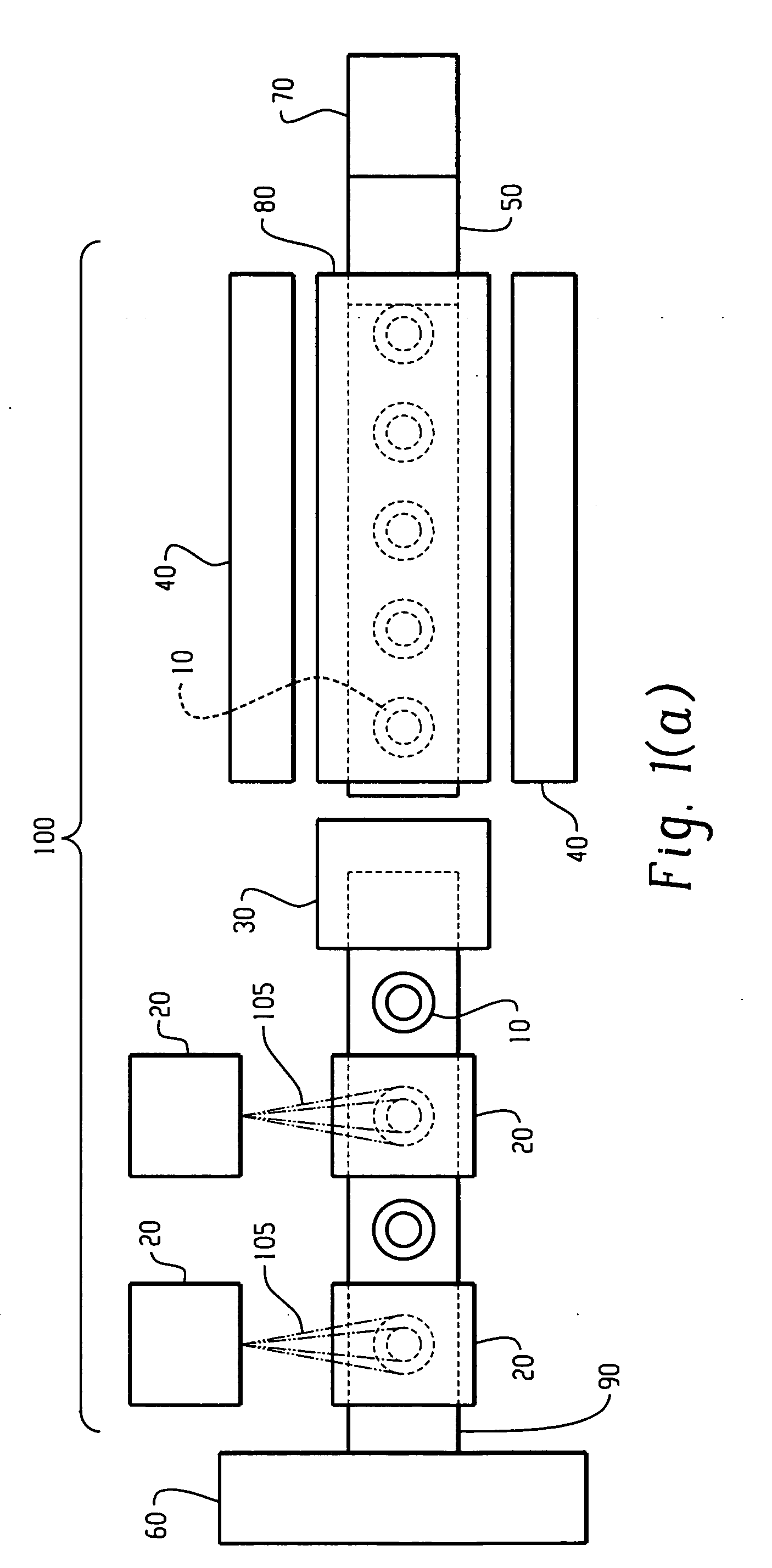
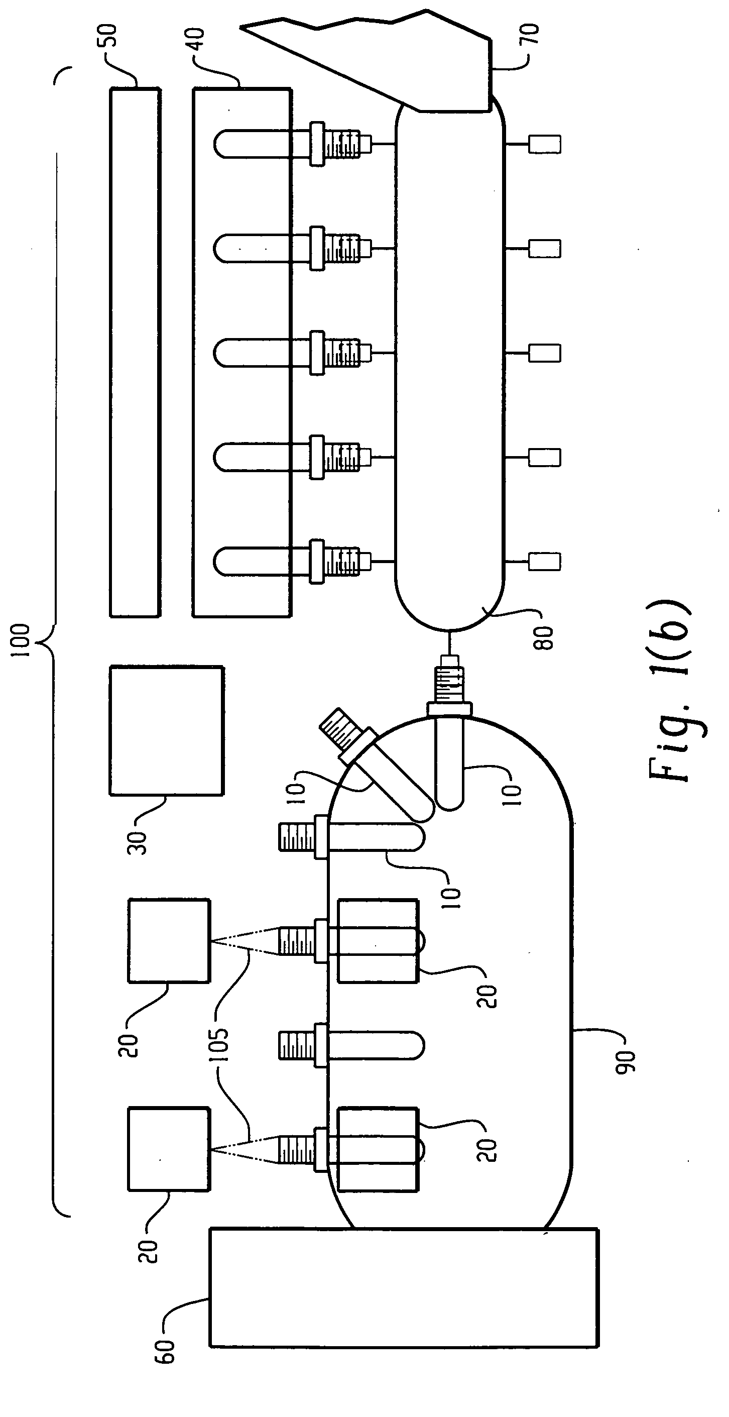
[0028] Referring to FIGS. 1(a) and (b), the components of a thermal conditioning section 100 include high-speed infrared temperature sensors 20 and an infrared temperature processing and control subsystem 30. The infrared temperature processing and control subsystem 30 interfaces directly with t...


PUM

PropertyMeasurementUnit
Temperatureaaaaaaaaaa
Frequencyaaaaaaaaaa

Abstract

A stretch blow molding system that condition preforms such that the temperature distribution within the cross-section of each preform is optimized prior to blow molding operations is provided. The system has a temperature measurement and control system capable of directly monitoring both the outside as well as inside surface temperature of preforms at different stages of transport throughout the thermal conditioning section of the system.

Description

BACKGROUND OF THE INVENTION [0001] This invention is directed to blow molding systems. More specifically, it is directed to stretch blow molding systems that condition preforms such that the temperature distribution within the cross-section of each preform is optimized prior to blow molding operations. [0002] By way of background, one of the most critical process variables when attempting to stretch blow mold certain materials is the temperature distribution of the preform as it is being blown. This variable often has a significant impact on the most important physical properties of the final blown article. Ideally, the preform wall cross-sectional temperature distribution should be optimized for blow molding operations. In addition, it is advantageous within an automated blow molding process if preforms that are moving through the system are consistent in temperature profile, one preform to the next. In more specific terms, it is advantageous for both the inside and outside surface...

Claims


Application Information

Patent Timeline
07 Jul 2005
Publication
US20050146065A1
IPC
B29C49/06; B29C49/78
CPC
B29C49/06; G01J5/62; G01J5/061; B29C49/78; G01J5/0805; B29C2949/0715; B29C2049/7861; B29C2049/78805
Inventors
COCHRAN, DON W.; CECH, STEVEN D.