Dial operating device

a technology of dial operation and dial 3 position, which is applied in the direction of mechanical control devices, gearing, instruments, etc., can solve the problem of excessive operation feeling at the intermediate position of the dial 3 position

Inactive Publication Date: 2001-05-01
KK TOKAI RIKA DENKI SEISAKUSHO
View PDF7 Cites 9 Cited by
  • Summary
  • Abstract
  • Description
  • Claims
  • Application Information

AI Technical Summary

Problems solved by technology

Therefore, the operation feeling at an intermedi

Method used


Image

  • Dial operating device
  • Dial operating device
  • Dial operating device

Examples


first embodiment

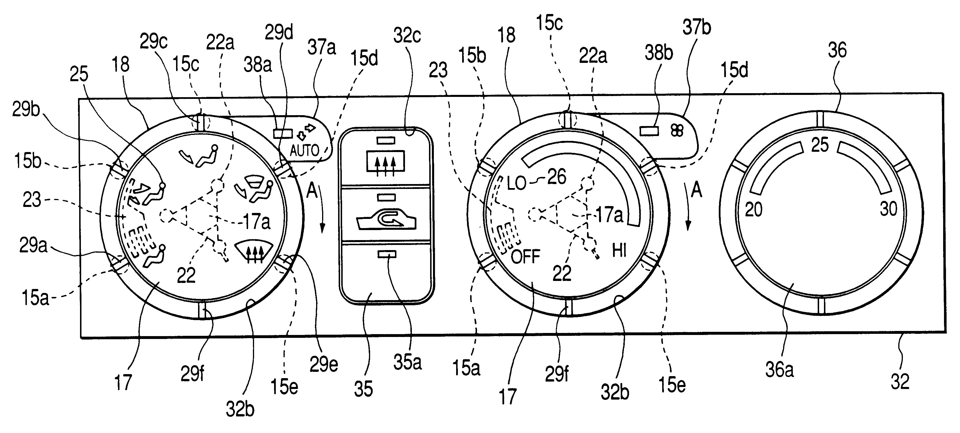
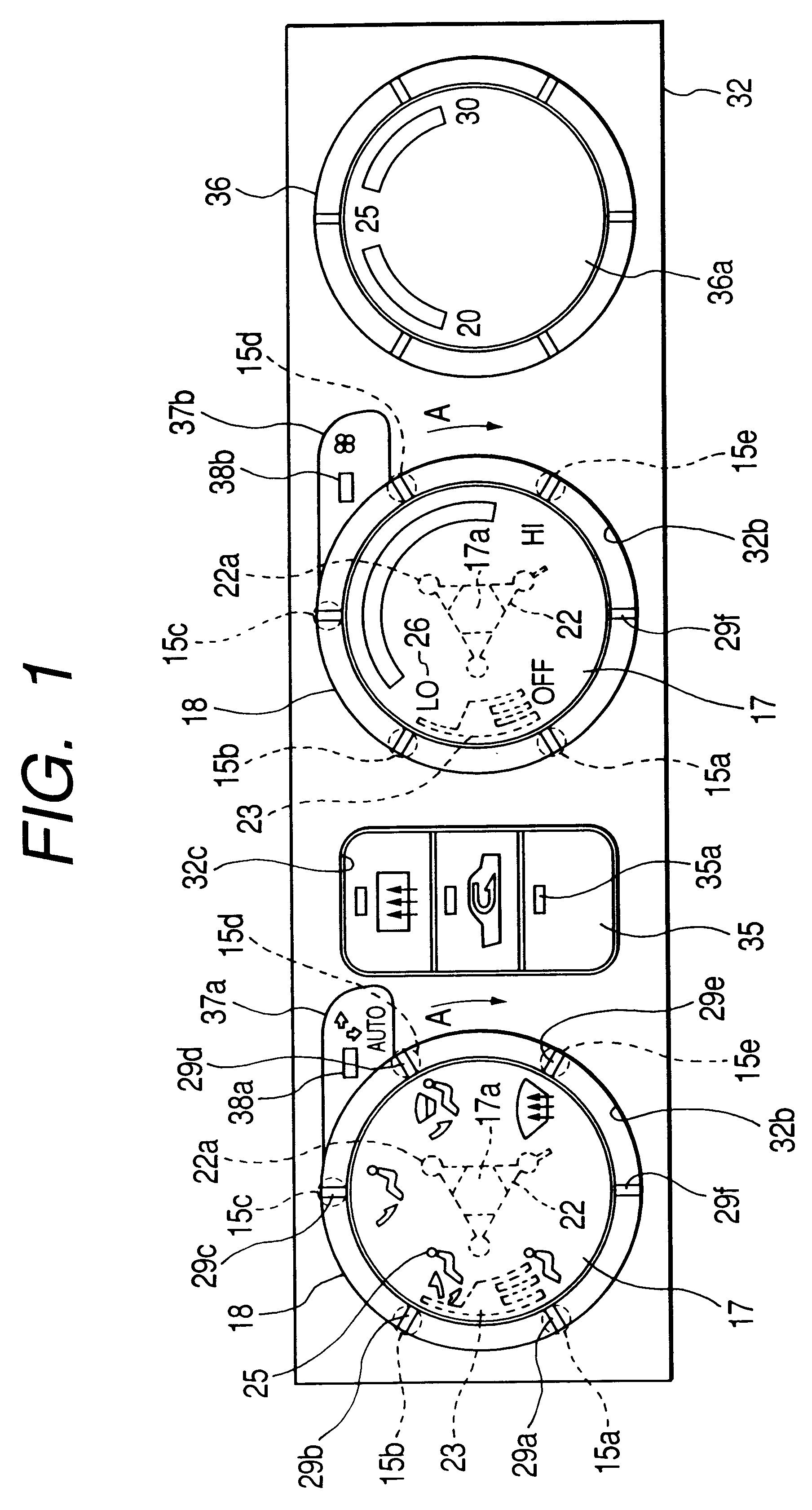
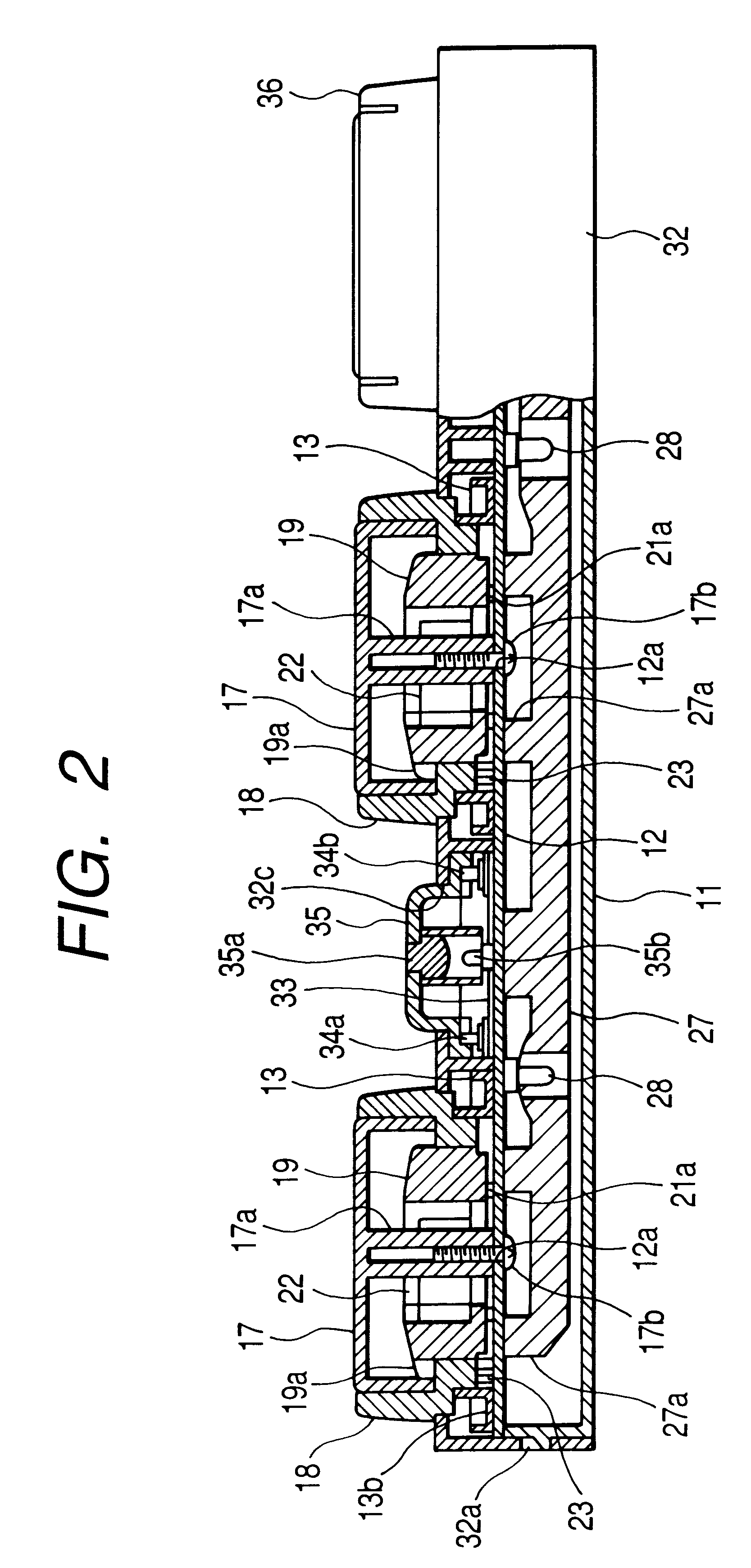
Referring to FIGS. 1 to 5, the present invention will be explained as follows. In this connection, this embodiment is a case in which the present invention is applied to a heater controller of an automobile, and this heater controller is attached onto an instrument panel of the automobile. As shown in FIG. 2, there is provided a bezel 32 made of synthetic resin. This bezel 32 is formed into a rectangular box-shape, the rear surface of which is open. A printed wiring board 12 is attached to the bezel 32 with screws, and a rear opening of the bezel 32 is covered with a printed wiring board 12 and a cover 11.

As shown in FIG. 4, holders 13, 13 made of synthetic resin are attached onto the front surface of the printed wiring board 12. An shown in FIG. 5, each holder 13 has six partition walls 13a which are integrated with the holder 13. Only four partition walls 13a are shown in FIG. 5. Between the partition walls 13a, there is formed an LED accommodating section 13b.

As shown in FIG. 3, ...

second embodiment

In the above second embodiment, two wire springs 39 are accommodated in the knob body 19 arranged on the left, and one wire spring 39 is accommodated in the knob body 19 arranged on the right. However, it should be noted that the present invention is not limited to the above specific embodiment. The number of the wire springs 39 may be adjusted if necessary.

In the above second embodiment, wire springs 39 are accommodated in both knob bodies 19. However, it should be noted that the present invention is not limited to the above specific embodiment. For example, when both the leaf spring 22 and the wire spring 39 are accommodated, intensities of forces to operate both knob dials 18 may be adjusted.

In the above first and the second embodiment, the second detection circuit patterns 31.sub.a1, 31.sub.a2 to 31.sub.e1, 31.sub.e2 for detecting the rotational directions of the knob dials 18 are formed on the printed wiring board 12. However, it should be noted that the present invention is no...


PUM


Abstract

When a leaf spring 22 is rotated integrally with the rotation of a knob dial 18, the leaf spring 22 is pushed and deflected by three corners of a cylindrical section 17a. After that, when three corners of the cylindrical section 17a get over the leaf spring 22 and new three surfaces are engaged with the leaf spring 22, rotation of the knob dial 18 is regulated. In this case, the pushing direction of the leaf spring 22 is the same as the direction of deflection. Therefore, the rotational resistance of the knob dial 18 can be reduced. Accordingly, a feeling of operation of the knob dial 18 becomes light.

Description

1. Technical Field of the InventionThe present invention relates to a dial operation device having a knob dial to be rotated for operation.2. Technical BackgroundFIGS. 7 and 8 are views showing a conventional structure of the above dial operation device. In this structure, there is provided a printed wiring board 1, onto which a support 2a of a knob base 2 is attached by screws. On an outer circumferential surface of the knob base 2, a knob dial 3 is pivotally engaged. A knob body 4 is engaged on an inner circumferential surface of the knob dial 3. Therefore, when the knob dial 3 is rotated for operation, the knob body 4 is rotated integrally with the knob dial 3.In the knob body 4, there is formed a moderation surface 4a. Engaging pieces 5, 5 are attached to the support 2a of the knob base 2. Both engaging pieces 5 are pushed by a compression spring 6. Therefore, both engaging pieces 5 can be engaged with recesses formed on the moderation surface 4a. Accordingly, when the knob dial...

Claims


Application Information

Patent Timeline
IPC IPC(8): H01H19/11H01H19/00H01C10/00H01H19/56
CPCH01H19/11Y10T74/20636
Inventor ISHIGURO, KAZUYOSHINAKA, MITSURU
Owner KK TOKAI RIKA DENKI SEISAKUSHO
Why Eureka
Try Eureka