Support device

a support finger and support technology, applied in the direction of machine supports, other domestic objects, mechanical apparatus, etc., can solve the problems of not being able to use less rugged insulators in this situation, current insulators, wires not being able to support the lower support finger, etc., to achieve less tooling costs and weaken the support finger

Inactive Publication Date: 2001-09-18
GALLAGHER ELECTRONICS LTD CO
View PDF20 Cites 19 Cited by
  • Summary
  • Abstract
  • Description
  • Claims
  • Application Information

AI Technical Summary

Benefits of technology

Another advantage of the present invention is that when the insulator is placed in its second orientation the support fingers which actually support the wire, have not been adapted so that they are incapable of supporting the wire when it is placed under an increased load. Hence in any circumstances, for example, in schools during the day where it is desirable to have an electric fence which also allows people to climb the fence (ie. when the f

Problems solved by technology

The function of the upper support finger is to prevent any movement of the wire, (for example by wind) which could lead to the wire being no longer able to be supported by the lower support finger.
However there is a problem associated with current insulators when they are used

Method used


Image

  • Support device
  • Support device
  • Support device

Examples


Embodiment Construction

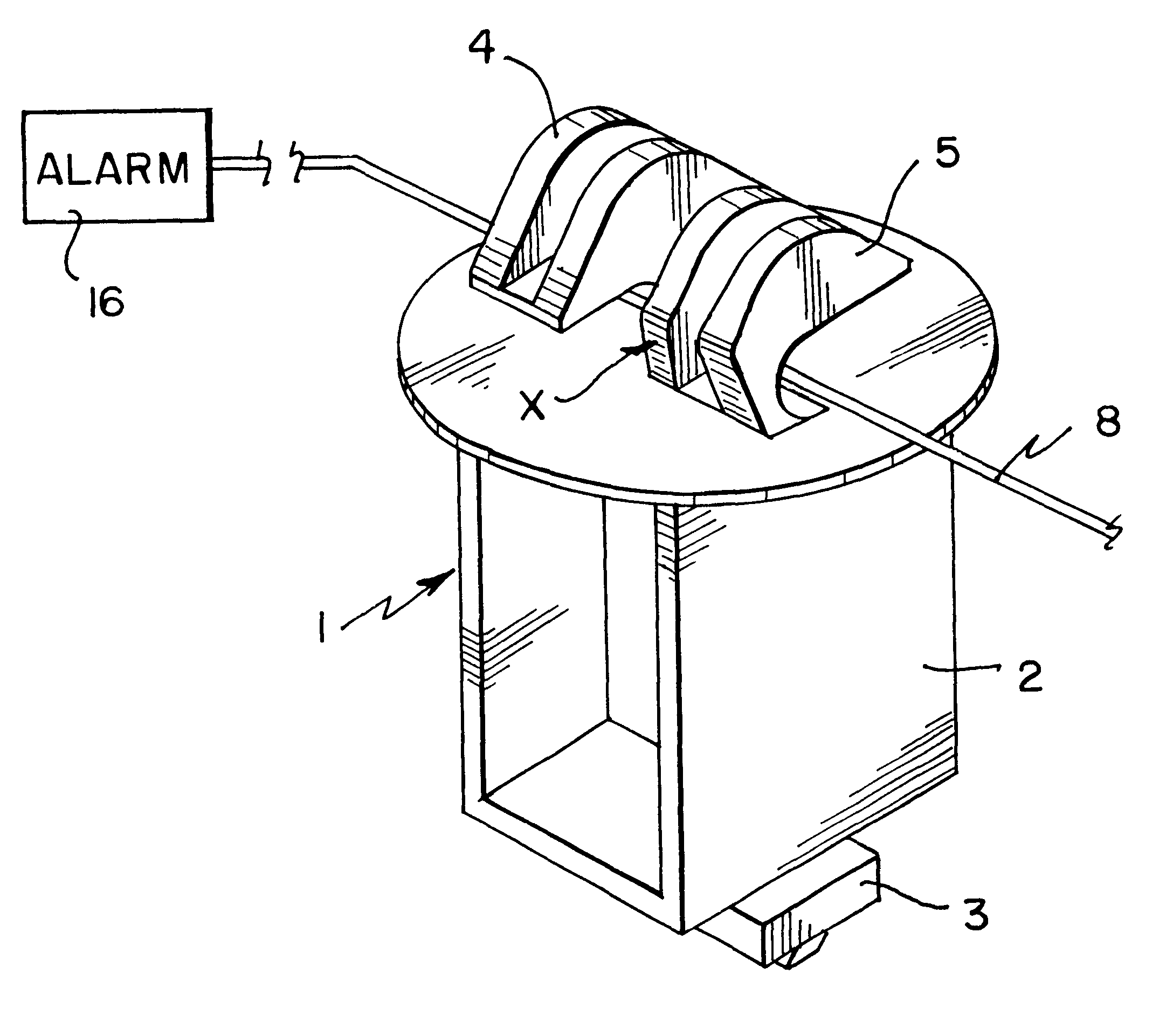
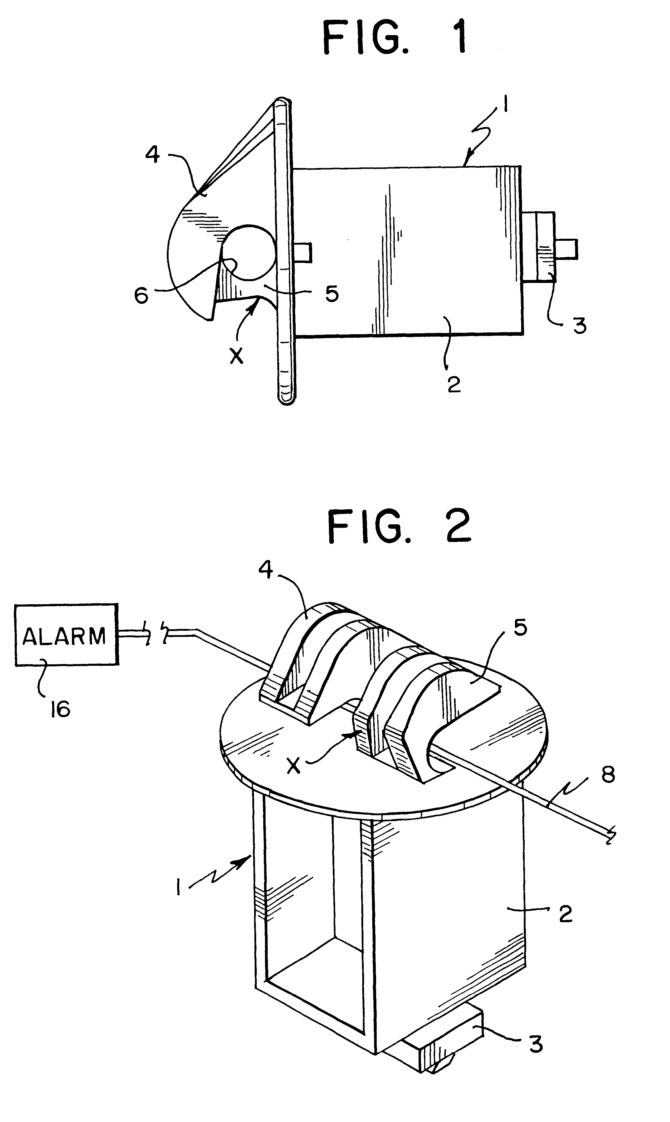
With respect to the drawings, there is provided an insulator indicated by arrow 1.

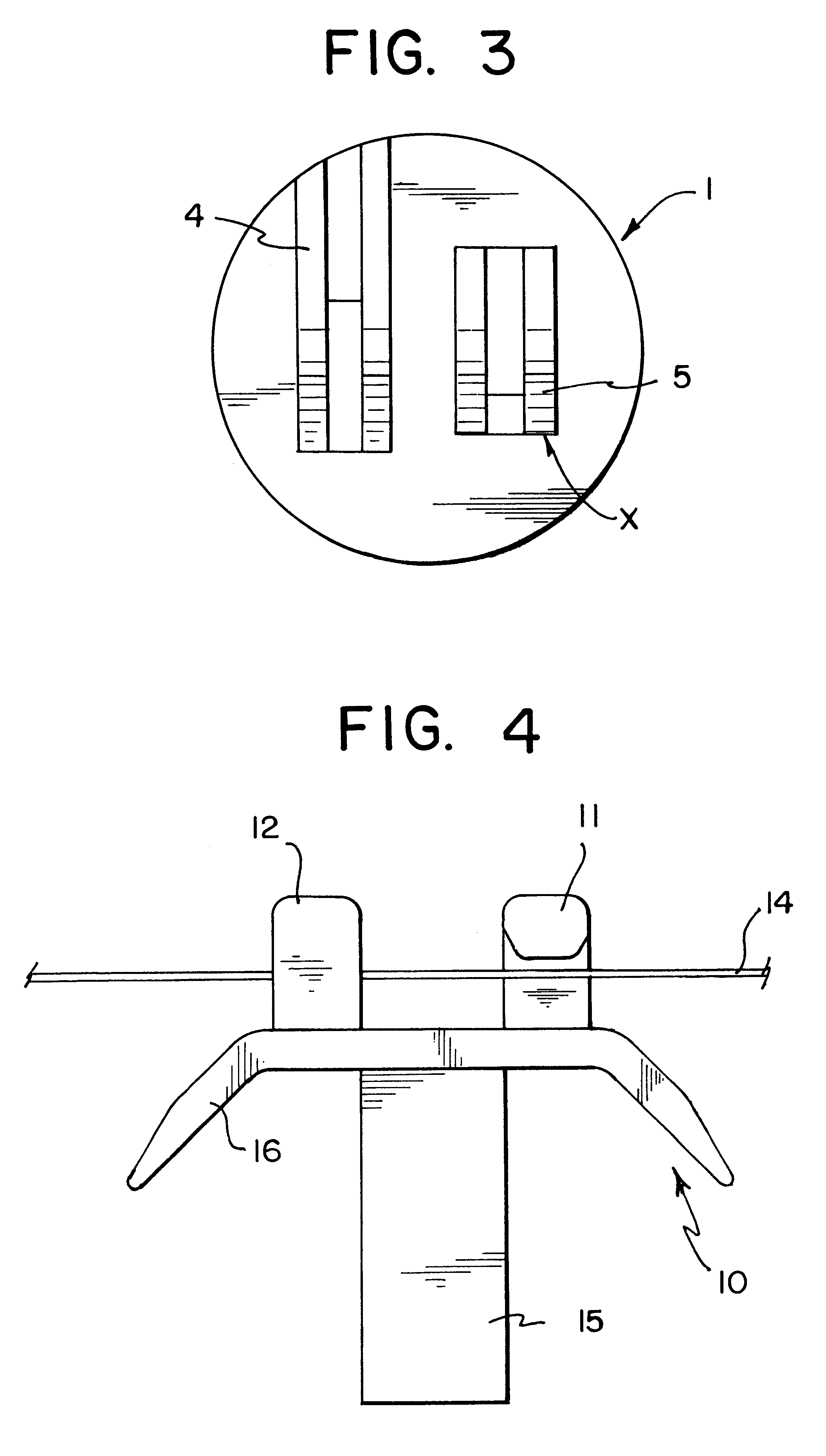
The insulator comprises a main body 2, an attachment device 3 and support fingers 4,5 which create an aperture 6 capable of containing a wire 8 (shown in FIG. 2).

The insulator 1 is attached to a external support means (not shown) by the attachment device 3. The attachment means 3 allows the insulator to be clipped onto the external support.

The insulator 1 is able to create an effective security fence as one of the support fingers 5 of the insulator 1 is adapted so that it cannot support the wire 8 when it is placed under an increased load. In the embodiment depicted support finger 5 has a weaker construction than that of support finger 4 as shown by arrow x. In the embodiments shown the weaker construction x of support finger may be achieved by cutting away or reducing the size of the finger 5 (see also FIGS. 2 and 3 where this is shown clearly).

Thus in a security fence when the insulator 1 has an orie...


PUM


Abstract

A support device (1) for supporting a length of material (8) wherein the support device includes: at least one support finger (4,5) for supporting the length of material (8) which applies an initial load to the support finger (5); the support device characterised in that the support finger (5) no longer supports the length of material (8) when the support finger is placed directly or indirectly under a load substantially greater than the initial load.

Description

This invention relates to a support device.In particular this invention relates to improvements in support devices used to support lengths of material utilised in fences.This invention will be discussed in relation to support devices used as insulators to support electrically conducting lengths of material, particularly in relation to security fences. However, it should be appreciated that the principles of the present invention can be applied to the support of many other non-electrically conducting lengths of material in various different situations.Insulators have been in use for many years for supporting and insulating the wires or other conductors used in electric fences.Existing insulators commonly have a backing surface and two support fingers for supporting the wire at attached to the backing surface. The fingers will now be referred to as upper and lower support fingers.These fingers are positioned so that the free end of the upper support finger is directed towards the fixe...

Claims


Application Information

Patent Timeline
IPC IPC(8): A01K3/00F16L3/06F16L3/02H01B17/14
CPCA01K3/005H01B17/145F16L3/06
Inventor KENDALL, GREGORY DAVID
Owner GALLAGHER ELECTRONICS LTD CO
Why Eureka
Try Eureka