Sheath flow cell and blood analyzer using the same

a technology of flow cell and blood analyzer, which is applied in the direction of laboratory glassware, instruments, chemistry apparatus and processes, etc., can solve the problems of low operating capability, difficult manufacturing and assembly of multi-structure nozzles, and high cos

Inactive Publication Date: 2002-04-02
SYSMEX CORP
View PDF12 Cites 69 Cited by
  • Summary
  • Abstract
  • Description
  • Claims
  • Application Information

AI Technical Summary

Problems solved by technology

Such flow cytometers are desired to provide enhanced operating capability as well as more functions, but they have the disadvantage that measurement using the sheath flow cell and washing thereof take a lot of time.
However, such a multi-structure nozzle is difficult to be manufactured and assembled and is expensive because of its complicated structure.
Furthermore, the operating capability is not expected to improve so much because all the passages of t...

Method used


Image

  • Sheath flow cell and blood analyzer using the same
  • Sheath flow cell and blood analyzer using the same
  • Sheath flow cell and blood analyzer using the same

Examples


Embodiment Construction

Now the present invention is described in detail with reference to an example as shown in the accompanying figures. Elements common to the figures are denoted by the same reference numerals and marks.

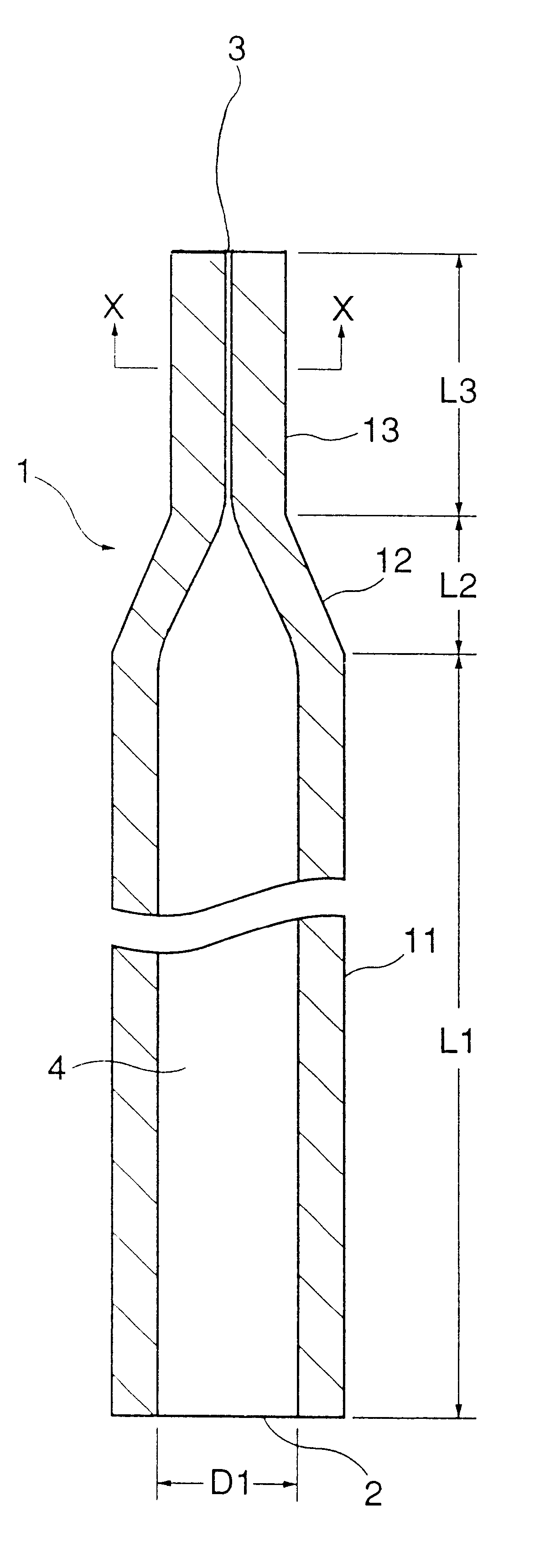
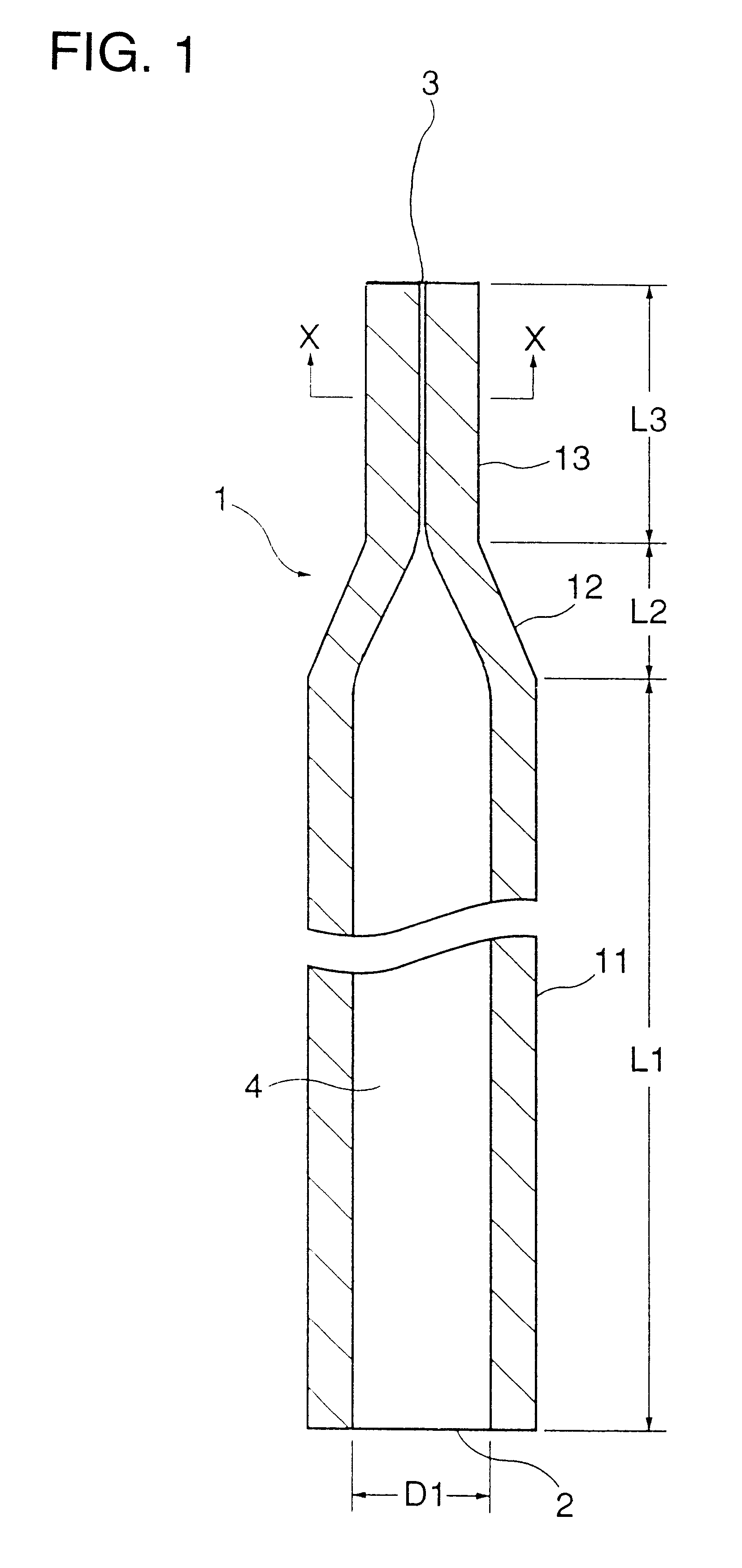
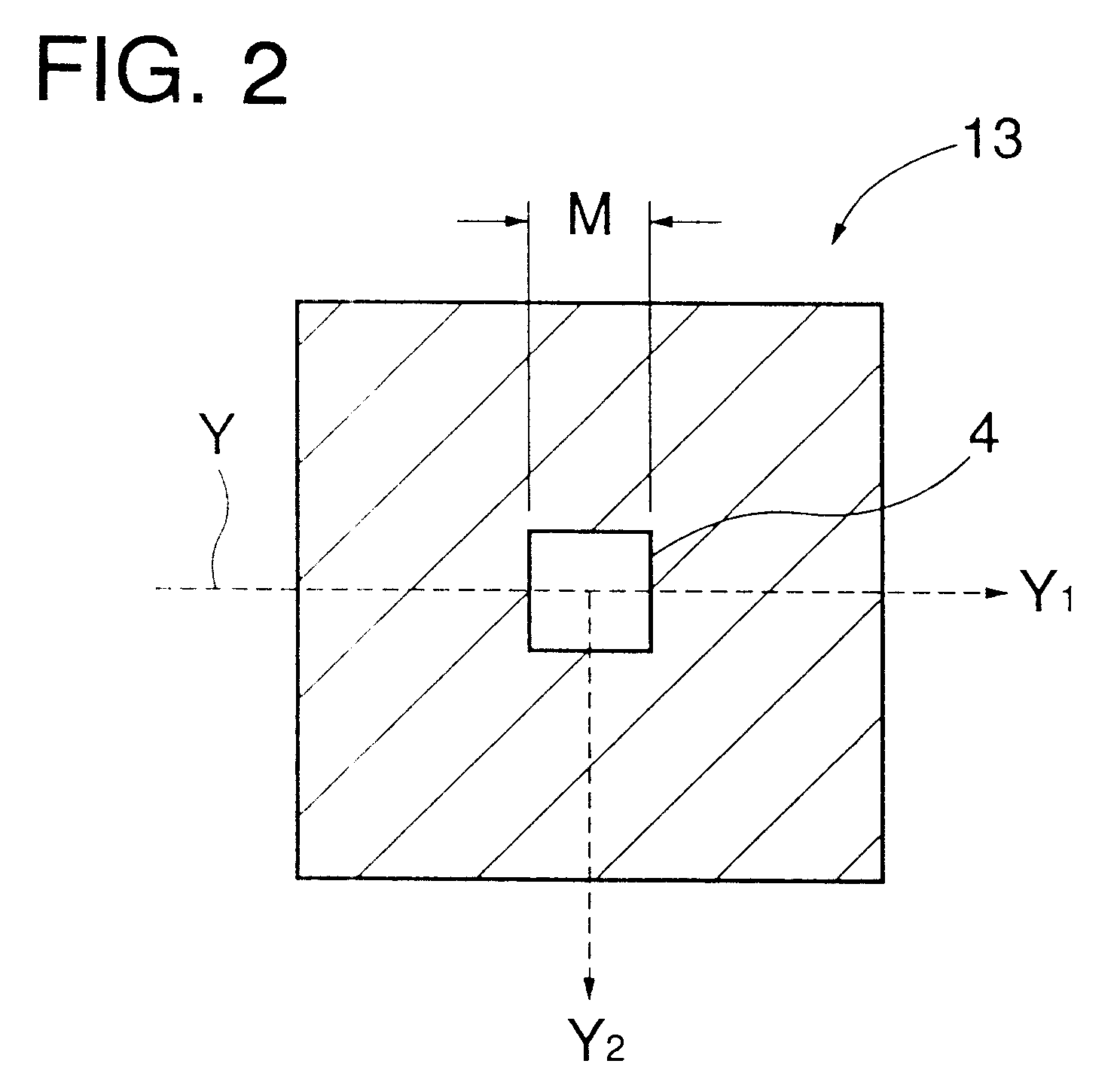
This example uses a flow cell 1 whose configuration is shown in FIGS. 1 and 2 and which has dimensions of D1=5 mm, L1=50 mm and M=0.2 mm. The cell 1 is integrally formed by fusion-bonding a rectifying section 11, an acceleration section 12 and an orifice section 13 which are each formed of quartz glass.

As shown in FIG. 3, the cell 1 is fixed to a fixing element 5 together with a nozzle 6. A sheath flow cell is thus constructed.

FIG. 6 is a perspective view illustrating an optical system of a blood analyzer of the present invention using the above-described sheath flow cell. In this figure, a beam emitted by a laser diode 21 illuminates the orifice section of the sheath flow cell 23 via a collimating lens 22. Forward scattered light emitted by blood cells passing through the orifice secti...


PUM


Abstract

A sheath flow cell includes a cell having a guide hole with an inlet and an outlet for guiding a sheath liquid. The cell has a rectifying section, an accelerating section and an orifice section having a cylindrical through-hole, a cone-shaped through-hole tapered toward the outlet and a prism-shaped through-hole with a square shaped section, respectively. The cylindrical, cone-shaped and square prism-shaped through-holes serially and smoothly communicating to each other so as to define the guide hole. There is a sample liquid supply nozzle having a cylindrical shape and extending from the inlet toward the accelerating section co-axially with the through-hole of the rectifying section. The through-hole of the orifice section has a cross section having a side length along its length square of 0.1 mm to 0.4 mm and the through-hole of the rectifying section has an axial length four or more times greater than its inner diameter.

Description

This application is related to Japanese Patent Application No. Hei11(1999)-13293 filed on Jan. 21, 1999, whose priority is claimed under 35 USC .sctn.119, the disclosure of which is incorporated by reference in its entirety.1. Field of the InventionThe present invention relates to a sheath flow cell and a blood analyzer using the same, more particularly to a sheath flow cell applicable to a sheath flow system and a multi-parameter blood analyzer using the same.2. Description of Related ArtFlow cytometers utilizing a so-called sheath flow system are well known as apparatus for analyzing particles such as cells or blood cells in samples. In this system, a sheath liquid envelops and pinches a sample liquid (which contains particles) discharged from a nozzle so that the sample liquid flows thinly in a sheath flow cell, where optical measurement is carried out for counting and analyzing particles in the sample liquid. The term "sheath flow" means a flow in which a flow of a floating part...

Claims


Application Information

Patent Timeline
IPC IPC(8): G01N15/14G01N33/49G01N33/487G01N15/00G01N21/05
CPCG01N15/1404G01N15/1456G01N2015/0076G01N2015/1402G01N2015/1411G01N2015/1006G01N2015/008
Inventor NAGAI, TAKAAKI
Owner SYSMEX CORP
Why Eureka
Try Eureka