Ducted fan vehicles particularly useful as VTOL aircraft

a technology of ducted fan and vtol aircraft, which is applied in the direction of airflow influencers, vertical landing/take-off aircraft, aircraft navigation control, etc., can solve the problems of collective control, vtol vehicles hover with sometimes zero forward airspeed, and vtol vehicles are usually more difficult to control than fixed wing aircraft in terms of stability and control

Inactive Publication Date: 2002-10-15
URBAN AERONAUTICS
View PDF11 Cites 116 Cited by
  • Summary
  • Abstract
  • Description
  • Claims
  • Application Information

AI Technical Summary

Benefits of technology

It has been found that such a vehicle equipped with a plurality of such vanes pivotally mounted across the inlet of the duct (as distinguished from the exit end of the duct) can indeed produce a combination of side forces with rotational moment that is favorable to the normal control of the vehicle. It has also been found that such vanes across the inlet end of the duct, particularly when combined with a second plurality of vanes across the outlet end of the duct, can produce desired forward, aft, left and right translation movements, as well as yaw, pitch and roll rotary movement of the vehicle.

Problems solved by technology

VTOL vehicles are usually more challenging than fixed wing aircraft in terms of stability and control.
The main difficulty rises from the fact that, contrary to fixed wing aircraft which accelerate on the ground until enough airspeed is achieved on their flight surfaces, VTOL vehicles hover with sometimes zero forward airspeed.
The disadvantage of using collective controls, and especially cyclic controls, lies in their added complexity, weight and cost.
The main problem is usually the creation of rotational moments of sufficient magnitude required for control.
However, one problem associated with vanes mounted at the exit of the duct in the usual arrangement as described above, is that even if these are able to create some moment in the desired direction, they cannot do so without creating at the same time a significant side force that has an unwanted secondary effect on the vehicle.
For such vanes mounted below the vehicle's CG (which is the predominant case in practical VTOL vehicles), these side forces cause the vehicle to accelerate in directions which are usually counter-productive to the result desired through the generation of the moments by the same vanes, thereby limiting their usefulness on such vehicles.
However, in the VZ-6, the single wing and the discrete vanes were used solely for the purpose of creating a steady, constant forward propulsive force, and not for creating varying control moments as part of the stability and control system of the vehicle.
However these were fixed in angle and could not be moved in flight.

Method used


Image

  • Ducted fan vehicles particularly useful as VTOL aircraft
  • Ducted fan vehicles particularly useful as VTOL aircraft
  • Ducted fan vehicles particularly useful as VTOL aircraft

Examples


Embodiment Construction

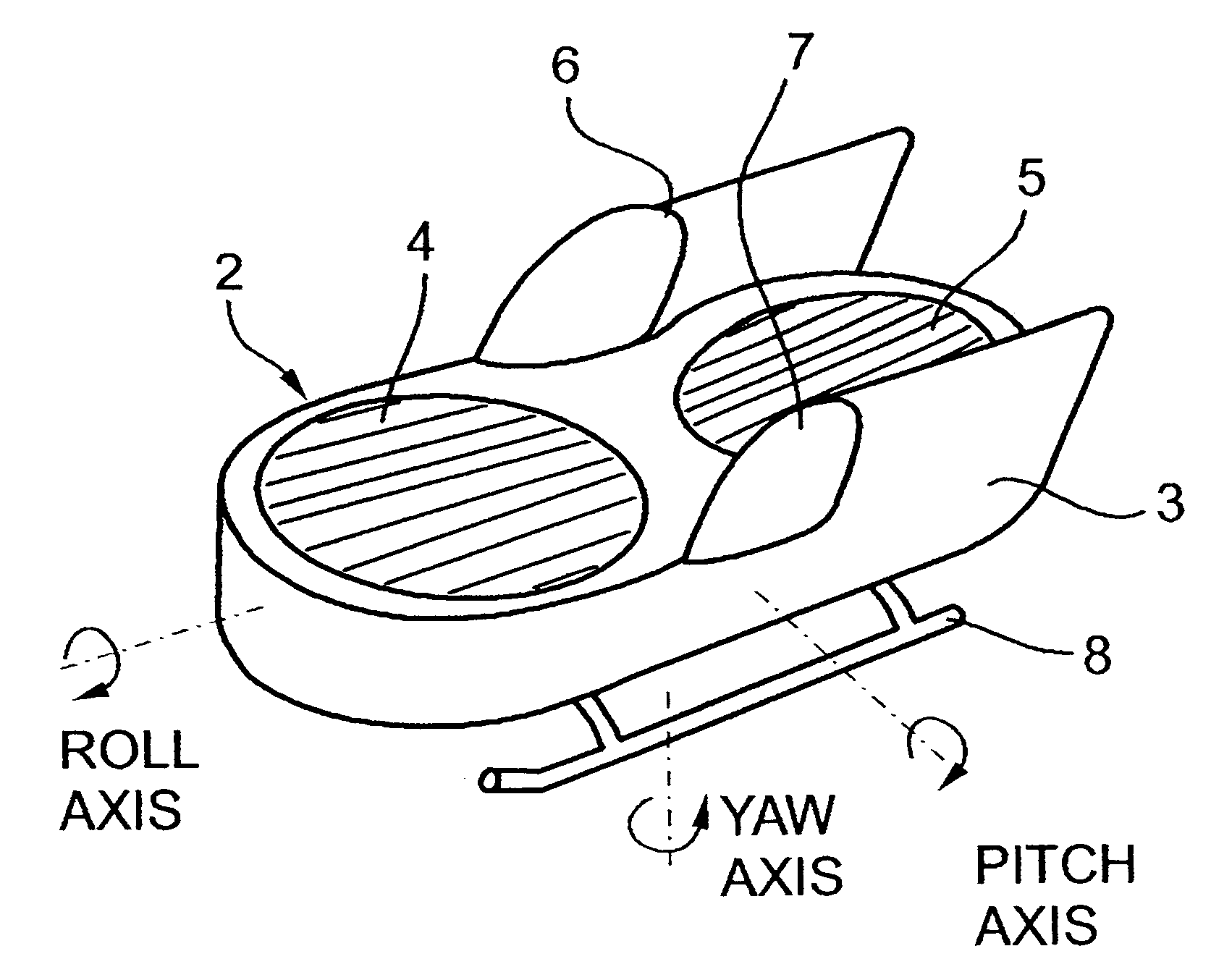
The vehicle illustrated in FIG. 1, and therein generally designated 2, is a VTOL aircraft including a frame or fuselage 3 carrying a ducted fan propulsion unit 4 at the front, and another similar propulsion unit 5 at the rear. The vehicle payload is shown at 6 and 7, respectively, on opposite sides of the fuselage, and the landing gear as shown at 8.

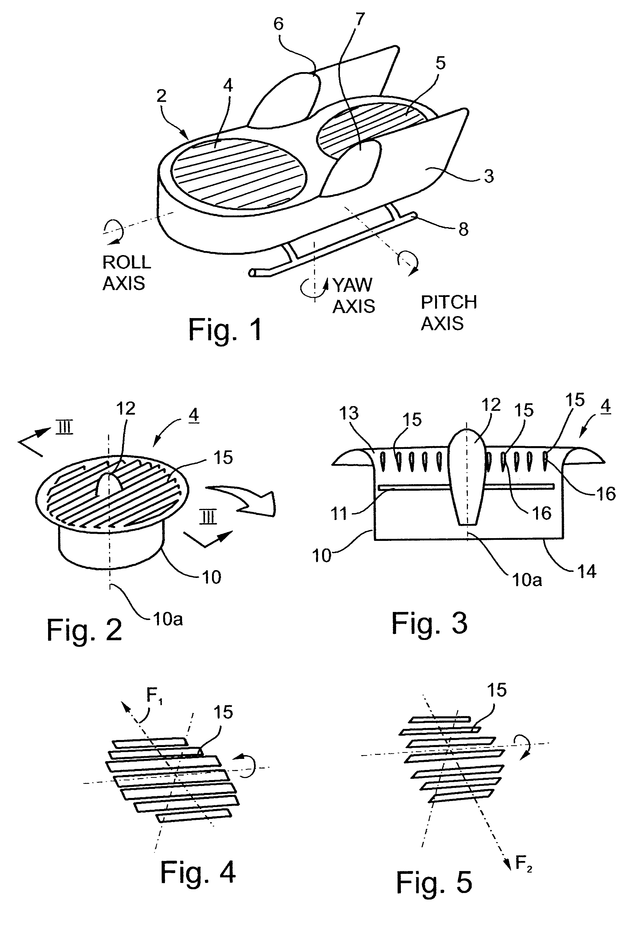
FIGS. 2 and 3 more particularly illustrate the structure of propulsion unit 4, which is the same as propulsion unit 5. Such a propulsion unit includes a duct 10 carried by the fuselage 3 with the vertical axis 10a of the duct parallel to the vertical axis of the vehicle. Propeller 11 is rotatably mounted within the duct 10 about the longitudinal axis 10a of the duct. Nose 12 of the propeller faces upwardly, so that the upper end 13 of the duct constitutes the air inlet end, and the lower end 14 of the duct constitutes the exit end. As shown particularly in FIG. 3, the upper air inlet end 13 is formed with a funnel-shaped mouth to produce...


PUM


Abstract

A vehicle, particularly a VTOL air vehicle, includes a duct carried by the vehicle frame with the longitudinal axis of the duct perpendicular to the longitudinal axis of the vehicle frame; a propeller rotatably mounted within the duct about the longitudinal axis of the duct to force an ambient fluid, e.g. air, therethrough from its inlet at the upper end of the duct through its exit at the lower end of the duct, and thereby to produce an upward lift force applied to the vehicle; and a plurality of parallel, spaced vanes pivotally mounted to and across the inlet end of the duct about pivotal axes perpendicular to the longitudinal axis of the duct and substantially parallel to the longitudinal axis of the vehicle frame. The vanes are selectively pivotal to produce a desired horizontal force component to the lift force applied to the vehicle. Various vane arrangements are disclosed for producing side, roll, pitch and yaw movements of the vehicle.

Description

FIELD AND BACKGROUND OF THE INVENTIONThe present invention relates to ducted fan vehicles, and particularly to such vehicles useful as VTOL (Vertical Take-Off and Landing) aircraft.Many different types of VTOL aircraft have been proposed where the weight of the vehicle in hover is carried directly by rotors or propellers, with the axis of rotation perpendicular to the ground. One well known vehicle of this type is the conventional helicopter which includes a large rotor mounted above the vehicle fuselage. Other types of vehicles rely on propellers that are installed inside circular cavities, shrouds, ducts or other types of nacelle, where the propeller or rotor is not exposed, and where the flow of air takes place inside the circular duct. Most ducts have uniform cross-sections with the exit area (usually at the bottom of the duct when the vehicle is hovering) being similar to that of the inlet area (at the top of the duct). Some ducts, however, are slightly divergent, having an exi...

Claims


Application Information

Patent Timeline
Patent Type & Authority Patents(United States)
IPC IPC(8): B64C27/20B64C29/00B64C27/00
CPCB64C27/20B64C29/0025
Inventor YOELI, RAFI
Owner URBAN AERONAUTICS
Why Eureka
Try Eureka