

Two-stroke internal combustion engine with crankcase scavenging
a two-stroke, internal combustion engine technology, applied in the direction of machines/engines, liquid fuel feeders, mechanical apparatuses, etc., can solve the problems of high nozzle pressure, high wear, carbon deposits, etc., and achieve the effect of reducing fuel losses and hydrocarbon emissions and increasing the service life of the injector
Inactive Publication Date: 2003-04-01
AVL LIST GMBH
View PDF9 Cites 25 Cited by
- Summary
- Abstract
- Description
- Claims
- Application Information
AI Technical Summary
Benefits of technology
to overcome these disadvantages and to propose a two-stroke internal combustion engine of the above type, where fuel losses and hydrocarbon emissions may be minimized in a simple manner for both high and low speeds and loads. Another object of the invention is to increase the service life of the injector.
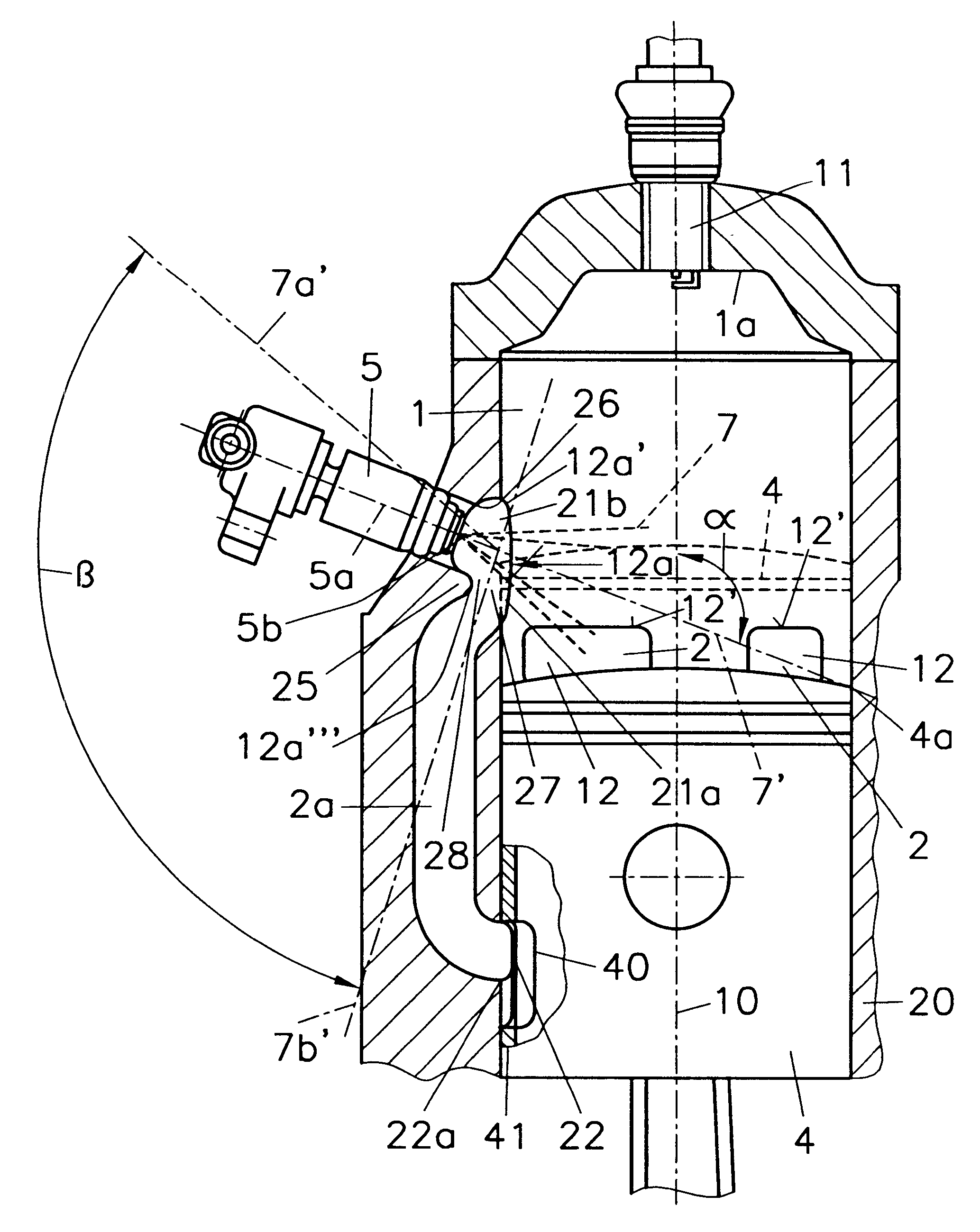
According to the invention this is achieved by providing that said cylinder wall comprises at least one recess and that at least one injector opens into said recess being arranged in close vicinity to said transfer window of said second transfer passage, wherein a narrow passage is arranged between said recess and said second transfer passage. Disposing the injector in the recess which communicates with the second transfer passage will considerably reduce carbon deposits as the air circulation prevailing in this region will afford cooling, and will enhance carburetion. Due to the narrow passage air flowing from the second transfer passage to the recess will be accelerated and therefore improve the cooling of the orifice of the injector.
Problems solved by technology
As the fuel injector is arranged near the entry of the auxiliary scavenging passage into the combustion chamber the temperature of the nozzle becomes very high resulting in carbon deposits and higher wear.
The drawback of this configuration is that strong scavenging losses are incurred in the lower speed range.
Moreover, the time available for an injection cycle is limited by the opening period of the scavenging windows.
For selection of the injector this may lead to problems with the dynamic range, i.e., the ratio of idle quantity to full-load quantity.
Because of the shortness of the injection period the fuel is injected onto the piston edge and piston rings, which will have negative effects on HC emissions and cause wetting of the cylinder wall and wash off the lubrication film.
This arrangement and the lack of air circulation around the injector will lead to high temperatures and an increase in carbon deposits at the injector nozzle.
Other undesirable results, which are caused by the direction of the injected fuel stream, will be the wetting of the cylinder wall and washing-off of the lubricating film.
The injector faces the exhaust window at a downward angle, which will result in strong scavenging losses in the lower speed range.
As the injector is positioned in that area of the cylinder wall that is swept during the compression stroke high temperatures and increased build-up of carbon deposits at the injector nozzle will occur due to the lack of air circulation.
Method used
View moreImage
Smart ImageViewing Examples

Examples
second embodiment
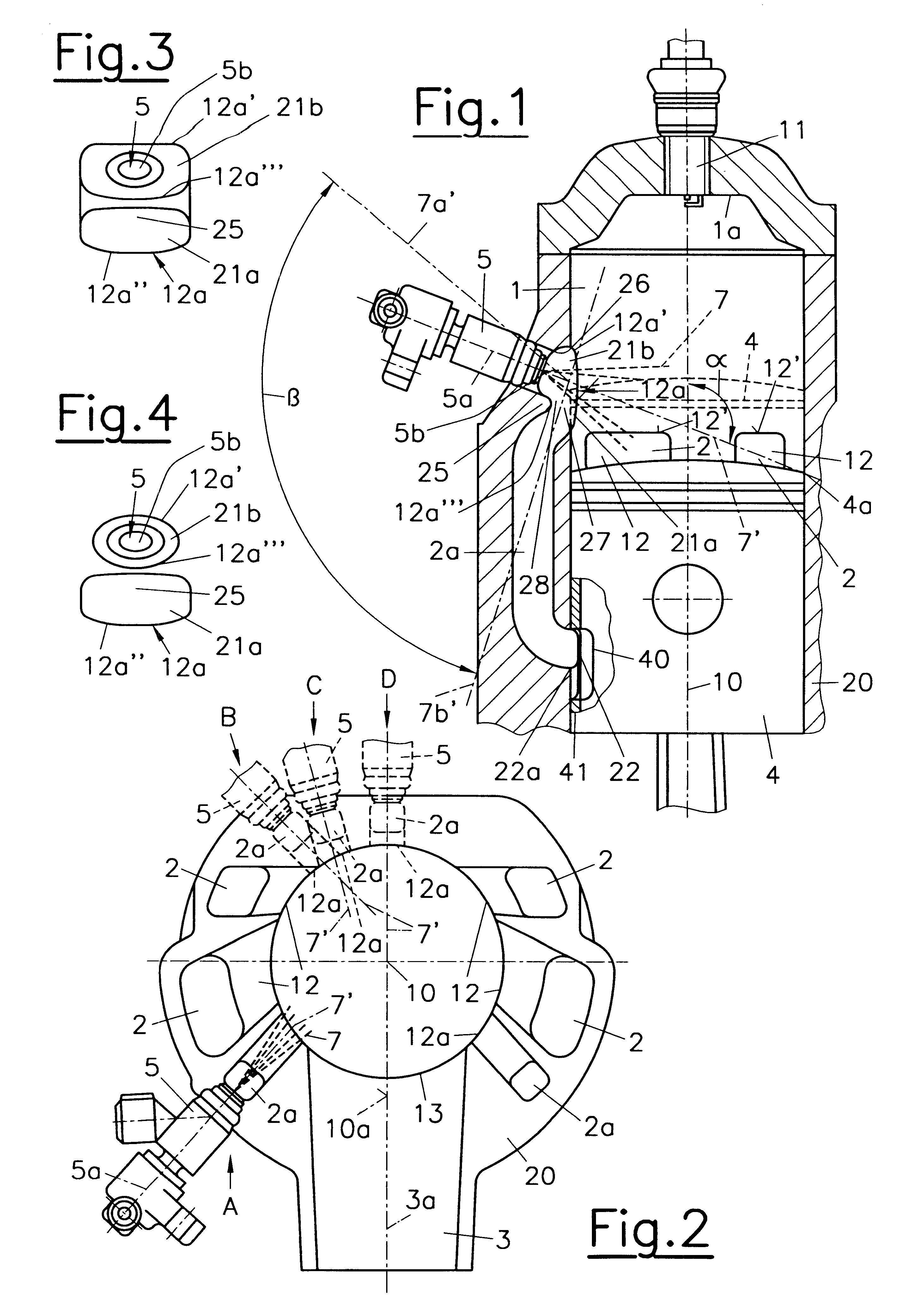
FIG. 4 is a detail view of the second transfer window in the invention,
third embodiment
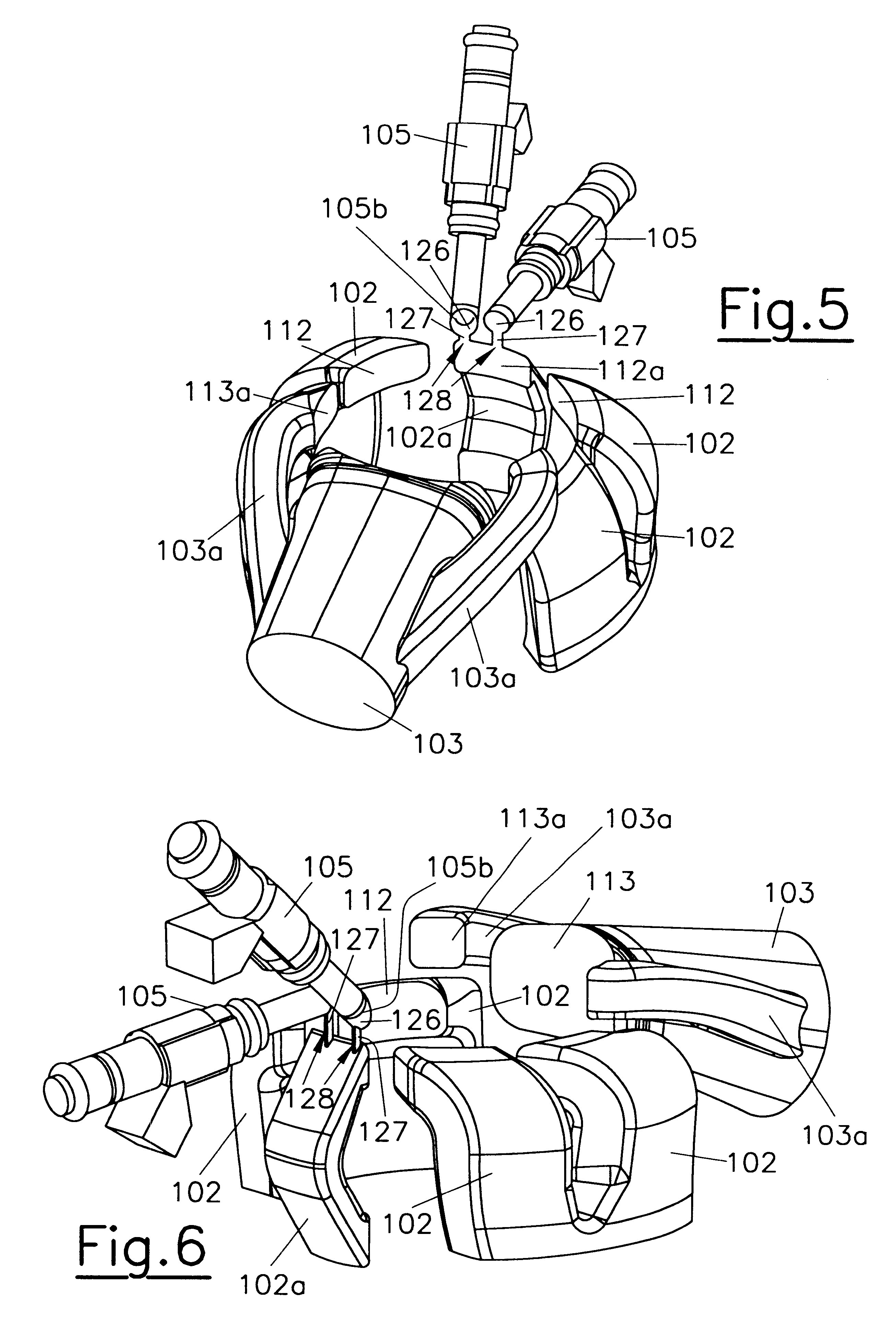
FIG. 5 is an oblique view of transfers passages in the invention, seen in the direction of the second transfer passage,
FIG. 6 is an oblique view of transfer passages in said third embodiment, seen in the direction of the exhaust passage,
fourth embodiment
FIG. 7 is an oblique view of transfer passages in the invention, seen in the direction of the second transfer passage,
FIG. 8 is an oblique view of transfer passages in said fourth embodiment, seen in the direction of the second transfer passage,
Login to View More PUM
 Abstract
The invention relates to a two-stroke internal combustion engine with crankcase scavenging, with an exhaust passage controlled by the piston and at least two first transfer passages and at least one second transfer passage, each with a corresponding transfer window into the cylinder chamber and a window on the crankcase side for communication between the cylinder chamber and the crankcase, the transfer windows of the first transfer passages being controlled by the upper edge of the piston, and the crankcase-side window of the second transfer passage being disposed in a region of the cylinder wall that is swept by the piston skirt of the piston. The cylinder wall comprises at least one recess, which is arranged in close vicinity to the transfer window of the second transfer passage and which is in flow communication with the second transfer passage, wherein a narrow passage is arranged between the recess and the second transfer passage.
Description
The invention relates to a two-stroke internal combustion engine with crankcase scavenging, with an exhaust passage controlled by the piston and at least two first transfer passages and at least one second transfer passage, each with a transfer window into the cylinder chamber and a window on the crankcase side for communication between the cylinder chamber and the crankcase, the transfer windows of the of the first transfer passages being controlled by the upper edge of the piston, and the crankcase-side window of the second transfer passage being disposed in a region of the cylinder wall that is swept by the piston skirt of the piston, wherein for control of the second transfer passage the piston skirt of the piston be provided with a control opening in the area of the crankcase side window of the second transfer passage.DESCRIPTION OF THE PRIOR ARTThe U.S. Pat. No. 3,881,454 describes a two-stroke engine construction with a pair of main scavenging passages and an auxiliary scaven...
Claims
Login to View More Application Information
Patent Timeline
 Patent Type & AuthorityPatents(United States)
IPC IPC(8): F02B25/20F02B25/14F02B25/00F02F1/22F02B33/04F02B33/02F02M69/04F02F1/18F02B75/02F02B75/00F02B75/12
CPCF02M69/045F02B25/14F02B25/20F02F1/22F02B33/04Y02T10/123F02B2075/025F02B2075/125Y02T10/12
InventorLAIMBOCK, FRANZ
OwnerAVL LIST GMBH