Brake with field responsive material

a technology of field responsive materials and brakes, which is applied in the direction of shock absorbers, mechanical equipment, transportation and packaging, etc., can solve the problems of limited space allotted for the use of these devices, and achieve the effect of restricting relative rotation

Inactive Publication Date: 2005-02-15
LORD CORP
View PDF26 Cites 80 Cited by
  • Summary
  • Abstract
  • Description
  • Claims
  • Application Information

AI Technical Summary

Benefits of technology

In one aspect of the present invention, a controllable brake includes a rotor having first and second rotor surfaces, an outer periphery and at least one working portion proximate to or at the outer periphery. A shaft has the rotor connected at one end of the shaft in a manner to restrain relative rotation therebetween. A housing includes a first chamber housing the rotor therein in a manner to allow rotation thereof (rotatably housing), and including a magnetic field generator spaced from the rotor, and configured and positioned for conveying a magnetic flux extending through controllable material between the field generator and working portion, in a direction toward the at least one working portion of the rotor. The controllable material is contained within

Problems solved by technology

Often, the space allotted for the use of these devices is limited and specific applications require that the

Method used


Image

  • Brake with field responsive material
  • Brake with field responsive material
  • Brake with field responsive material

Examples


first embodiment

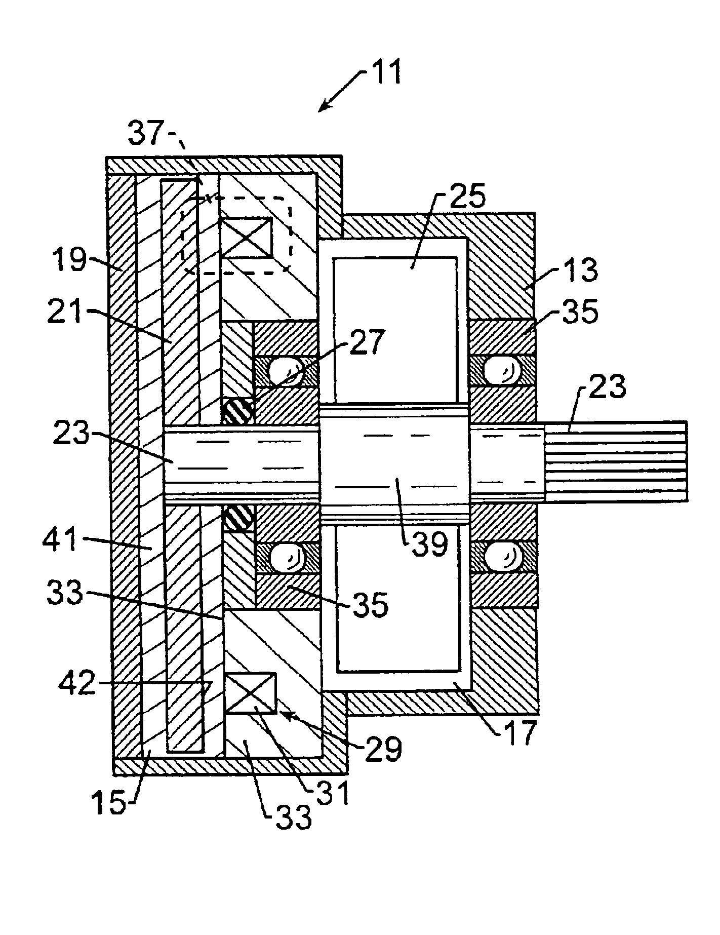
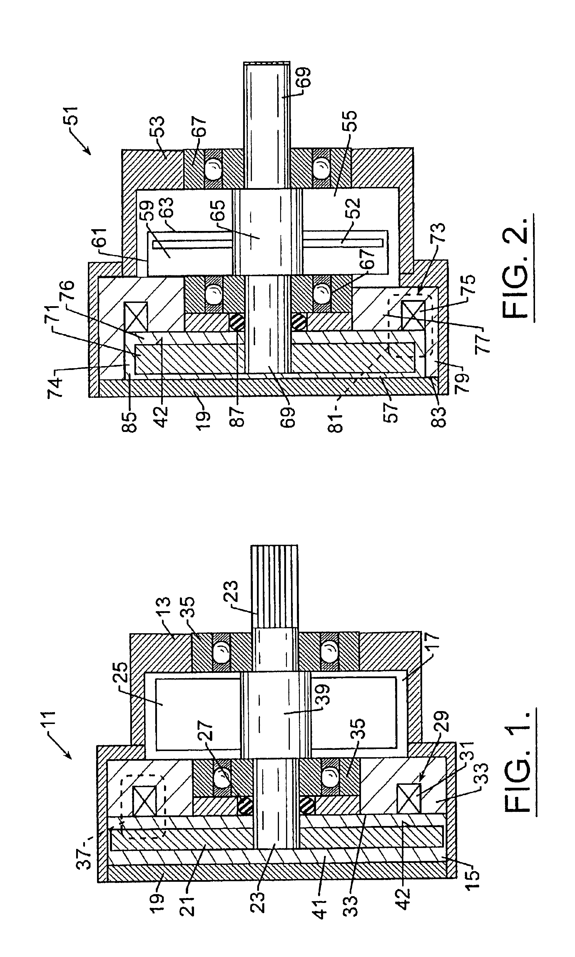
Now turning to the Figures wherein like parts are referred to by the same numbers in the several views, FIG. 1 illustrates the present invention. The brake 11 illustrated in FIG. 1 is a side coil brake. As the description proceeds it should be understood that although the term “brake” is used to describe the embodiments of the invention the invention is generally a torque generating device that creates a dissipative torque in response to signals received or generated by the device 11. For purposes of describing the preferred embodiments of the invention the field controllable material is disclosed as a free flowing material with particles randomly dispersed throughout the carrier medium. However, it is contemplated that the field controllable medium may also be comprised of a compacted material where the particles are fixed relative to adjacent particles.

Brake 11 includes a housing 13 having a first chamber 15 which houses rotor 21 for rotation therein. Optionally, a second housing ...

third embodiment

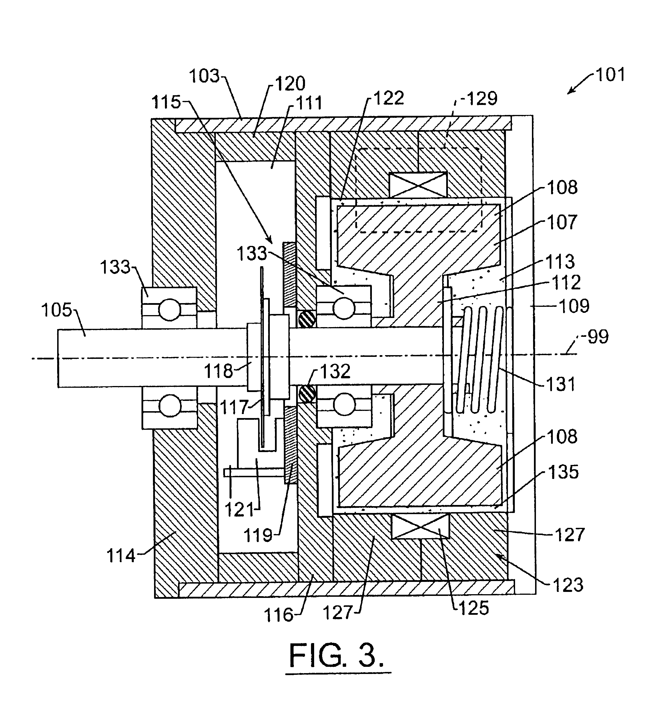
A third embodiment brake of the present invention is illustrated in FIG. 3 and is referred to generally at 101. Brake 101 comprises hollow, cylindrical housing 103 which defines a first chamber 113 for housing a rotor 107 for rotation therein about axis 99 and defines second chamber 111 which houses monitoring and / or controlling electronics 115 in the manner previously described. The first chamber also houses a volume of a field responsive material 135. The rotor is a drum-shaped rotor that comprises a substantially I-shaped cross section with a wide outer annular peripheral portion 108 joined by a narrow web 112. The rotor 107 is fixed in a conventional manner to one end of shaft 105 which in turn is supported by bearings 133 along the shaft length and generally in the manner previously described with first and second embodiment brakes 11 and 51. Closing plate 109 serves to seal and close one end of the housing 103. Plate 114 closes and seals the opposite housing end. The rotor may...

second embodiment

In the embodiment of FIG. 3, the seal 132 required to prevent migration of material 135 from the first chamber 113 to the second chamber 111 is shown seated in bearing support plate 116. Such a suitable seal may comprise the seal disclosed in the description of first and second embodiment brakes. The suitable conventional seal may be supported in the bearing support plate 116 or within bearings 133. An annular shroud 120 is located between plates 114 and 116. Shroud 120, in combination with plates 114 and 116 encloses the sensing means 115 within chamber 111.

Returning again to the rotor 107 of the third embodiment brake 101, rotor 107 is not substantially disk-shaped like disks 21 and 71 previously described. As shown in FIG. 3, rotor enlarged peripheral portion 108 is located proximate electromagnetic coil 125 of field generator generally identified at 123. As shown by the stippling representing field responsive material 135, an annular gap 122 separates the portion 108 and field g...


PUM


Abstract

A controllable brake includes a rotor supported on one shaft end. The rotor is housed within a chamber containing a field controllable material which is acted upon by a magnetic field generator to change the rheology of the material and thereby impede movement of the rotor. The shaft is supported by two bearings which, in combination with the housing define a second housing chamber adapted to enclose means for monitoring and/or controlling the brake and in this way, an integrated, compact controllable brake is provided.

Description

FIELD OF THE INVENTIONThe invention relates to the area of brakes, clutches, resistance generating devices and motion control devices. Specifically the invention relates to devices employing a field responsive material for controlling torque in rotary acting devices or linearly-acting devices.BACKGROUND OF THE INVENTIONDevices employing a field responsive material for damping and controlling vibration and shock are known. Such a field responsive material may comprise a suitable magnetorheological (MR) material well known to one skilled in the art. As the description proceeds, the field responsive material may be referred to as either “MR medium” or “MR material” or “field responsive material” or “field controllable material”. Additionally, for purposes of clarity throughout this disclosure, devices employing such a field controllable material will generally be referred to as either “magnetorheological devices” or “MR devices” or “field controllable devices” or “field responsive devi...

Claims


Application Information

Patent Timeline
IPC IPC(8): F16D63/00B62D5/00F16F9/53
CPCF16D57/002B62D5/005
Inventor JOLLY, MARK R.MARJORAM, ROBERT H.KOESTER, STEVEST. CLAIR, KENNETH A.
Owner LORD CORP
Why Eureka
Try Eureka