Cable management system

a management system and cable technology, applied in the field of electrical assemblies, can solve problems such as adding to the complexity of the system

Inactive Publication Date: 2005-02-15
ORACLE INT CORP
View PDF18 Cites 34 Cited by
  • Summary
  • Abstract
  • Description
  • Claims
  • Application Information

AI Technical Summary

Benefits of technology

According to another aspect, the invention provides a slider mechanism for supporting an electronics assembly and allowing the assembly to move into and out of a rack, which comprises:(i) a first part which, in use, is stationary, and(ii) a second part which, in use, is attached to and moves with the electronics assembly;(iii) a cable management system for supporting cables located at the rear of the assembly, which comprises an articulated arm having a first end which is attachable to the assembly and a second end which is mounted on the first part of the slider mechanism so that bending of the arm accommodates movement of the electronics a

Problems solved by technology

Their width is normally in the region of 19 inches (0.5 m), hence their name, but their depth can vary by quite a large degree, and it has been necessary to manufacture such cable management systems in a number of diff

Method used


Image

  • Cable management system
  • Cable management system
  • Cable management system

Examples


Embodiment Construction

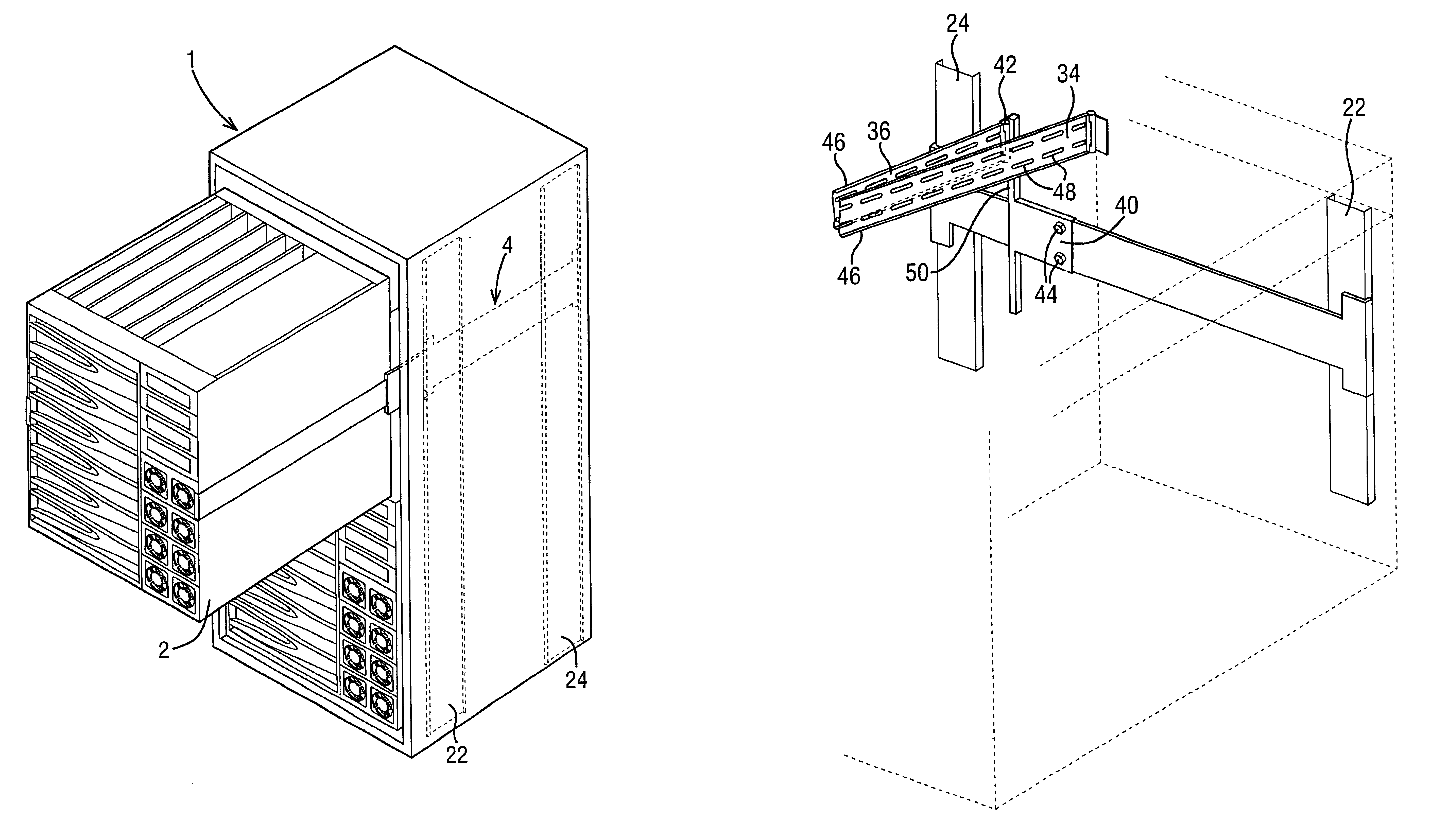
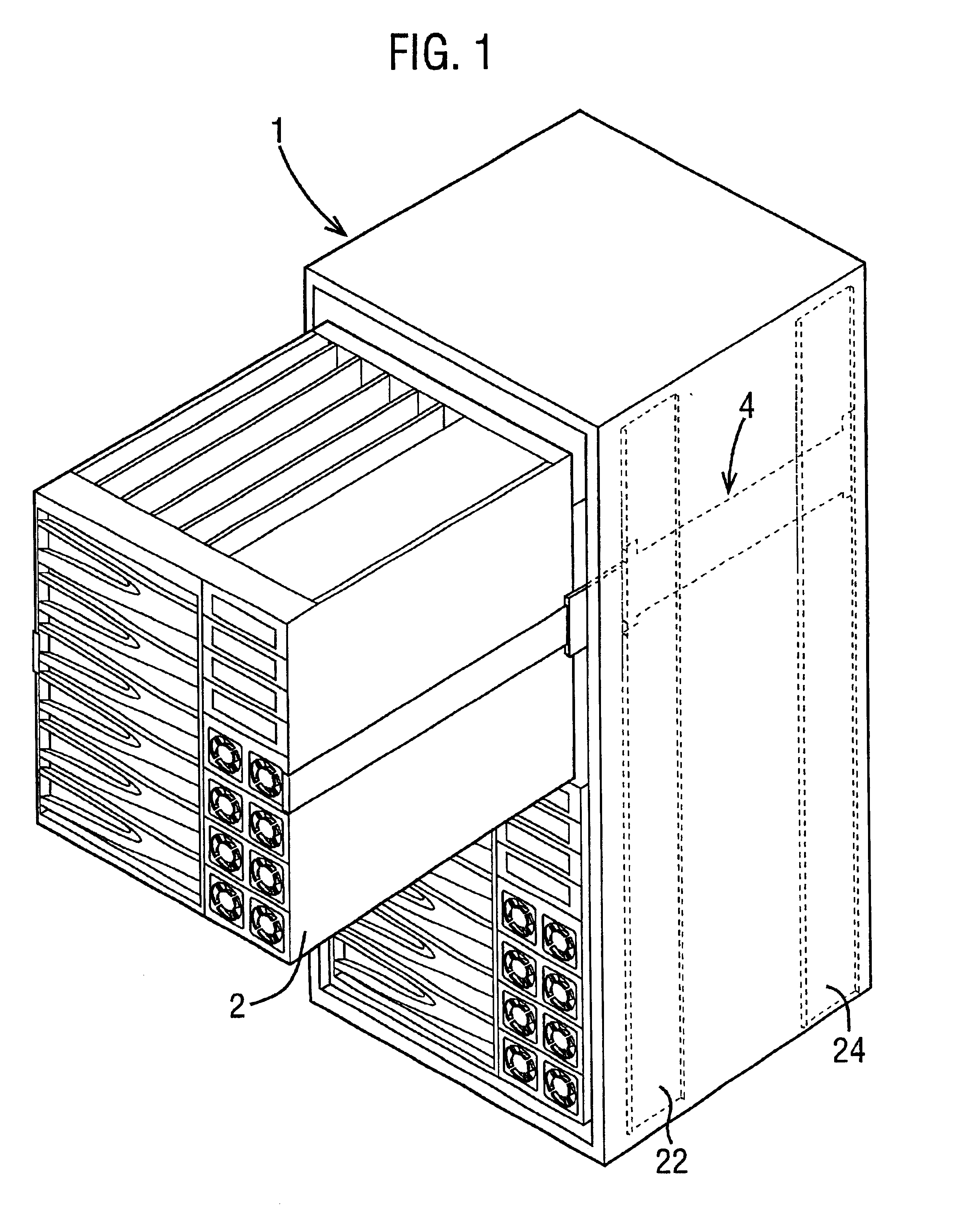
Referring now to the drawings, in which like reference numerals are used to designate corresponding elements, FIG. 1 shows an electronics cabinet 1 for a nineteen inch rack that houses a pair of electronics assemblies 2 although other sizes of cabinet may be employed. Such electronics assemblies may be employed for a number of services, for example as part of a local area network (LAN) or for telecommunications purposes. Each assembly typically comprises a chassis that contains a motherboard and a number of daughterboards that are arranged in parallel planes to one another and connected to the motherboard. In addition, other components such as power modules, hard disc drives, tape drives etc. may be present.

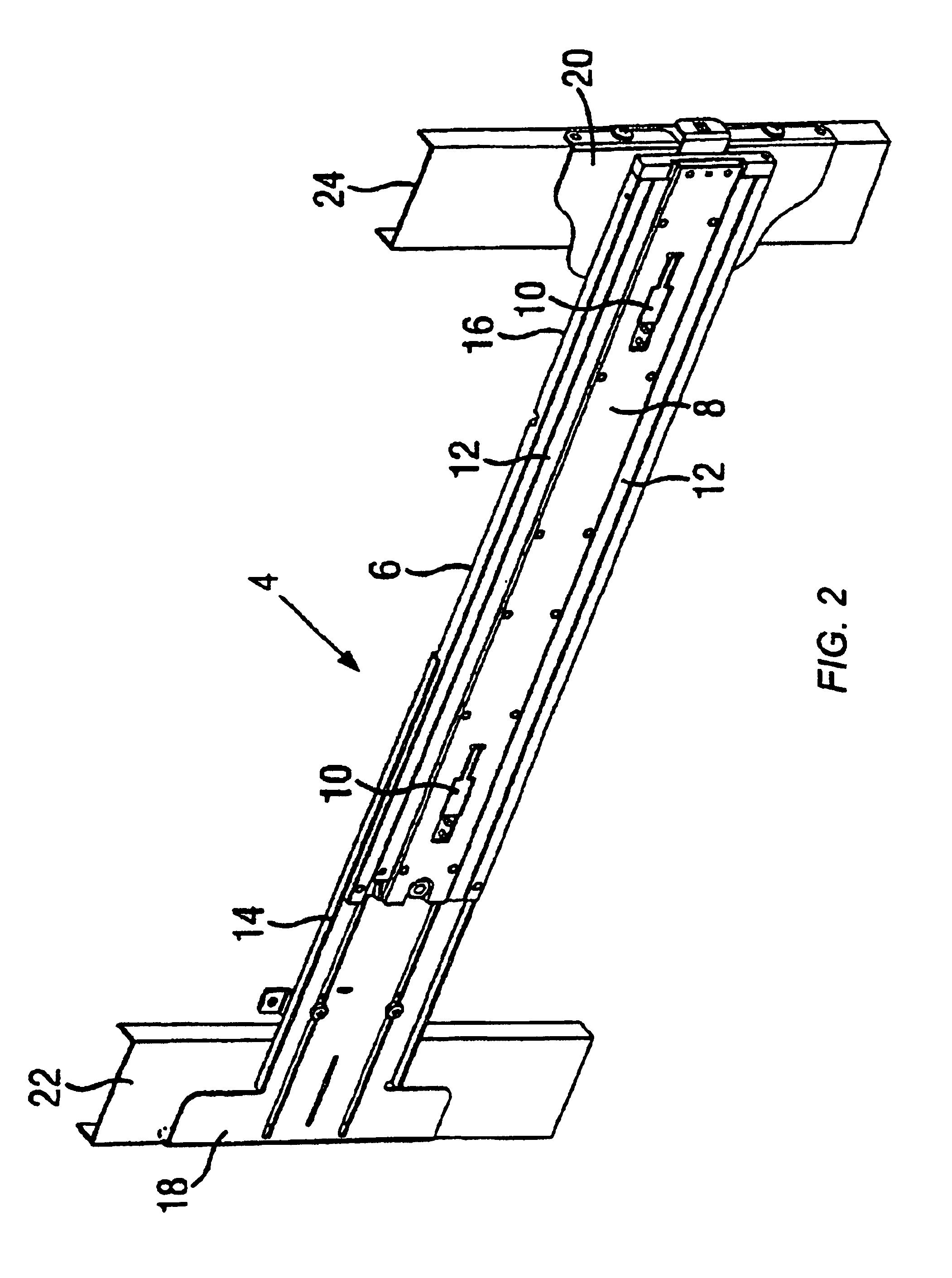
Both electronics assemblies 2 are supported within the cabinet 1 by means of slider mechanisms, each of which comprises a pair of telescopic sliders 4, one of which is located on each side of the cabinet (and therefore the assembly 2). One such telescopic slider 4 is shown in gre...


PUM


Abstract

A rack for an electronics assembly may have a supporting frame and a slider mechanism with a first part that is supported by the frame and a second part that supports the electronics assembly. The slider mechanism may be configured to allow the assembly to be moved out of the rack. The rack may further include a cable management system for supporting cables located at the rear of the assembly. The cable management system may have an articulated arm with a first end coupled to the assembly and a second end coupled to the first part of the slider mechanism so that bending of the arm accommodates movement of the electronics assembly. The cable management system may allow the assembly to be pulled out of the rack by the required distance irrespective of the depth of the rack.

Description

BACKGROUND OF THE INVENTIONThe present invention relates to electronics assemblies, and is primarily concerned with racked assemblies. Many such assemblies will be located in racks for housing in for example nineteen inch cabinets, or other size cabinets such as twenty three inch or metric cabinets. The assemblies may for instance be employed as servers for a number of systems, for example in local area networks (LANS), wide area networks (WANs), telecommunications systems or other operations such as database management or as internet servers.Such an assembly will typically comprise a supporting chassis that houses a motherboard or backplane and a number of daughterboards or module cards that extend in planes generally perpendicular to the plane of the motherboard and which are connected to the motherboard by connectors, e.g. high density connectors, so that the daughterboards can simply be located on guides and pushed toward the motherboard in order to connect them to it. An assemb...

Claims


Application Information

Patent Timeline
IPC IPC(8): H05K7/14
CPCH05K7/1491
Inventor WRYCRAFT, SEAN CONOR
Owner ORACLE INT CORP
Why Eureka
Try Eureka