Intersomatic implants in two parts

Inactive Publication Date: 2005-02-15
STRYKER EURO OPERATIONS HLDG LLC
View PDF28 Cites 121 Cited by
  • Summary
  • Abstract
  • Description
  • Claims
  • Application Information

AI Technical Summary

Benefits of technology

In embodiments where the intention is to position an implant whose body has lateral walls provided with through-openings extending between the upper and lower faces of the body, the method c

Problems solved by technology

These known implants have the disadvantage that they are more expensive and difficult to manufacture

Method used


Image

  • Intersomatic implants in two parts
  • Intersomatic implants in two parts
  • Intersomatic implants in two parts

Examples


second embodiment

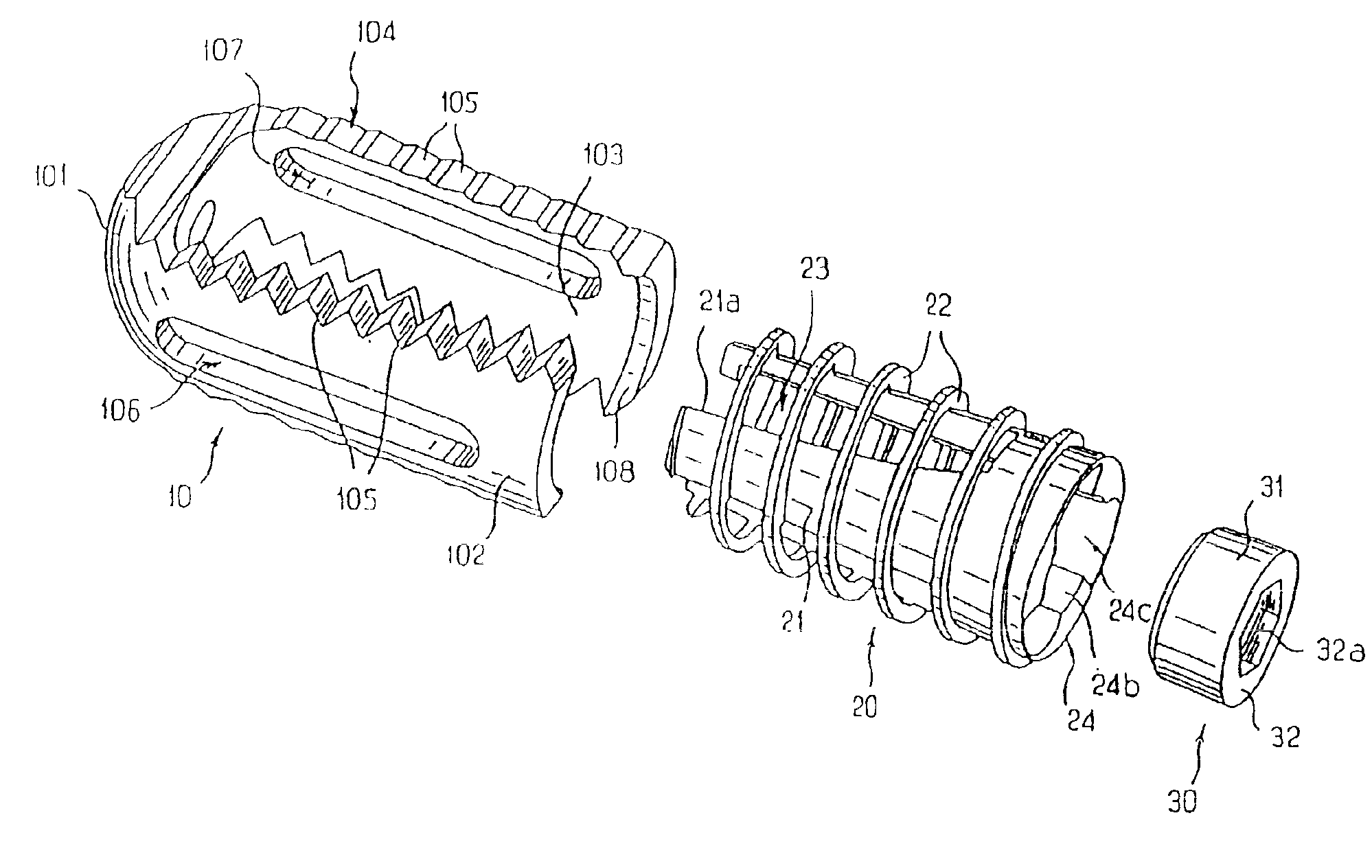
FIGS. 9 to 15 illustrate the present invention.

In these figures, elements or parts which are identical or similar to those in FIGS. 1 to 8 are designated by the same reference labels, and only the differences between this second embodiment and the first will be described.

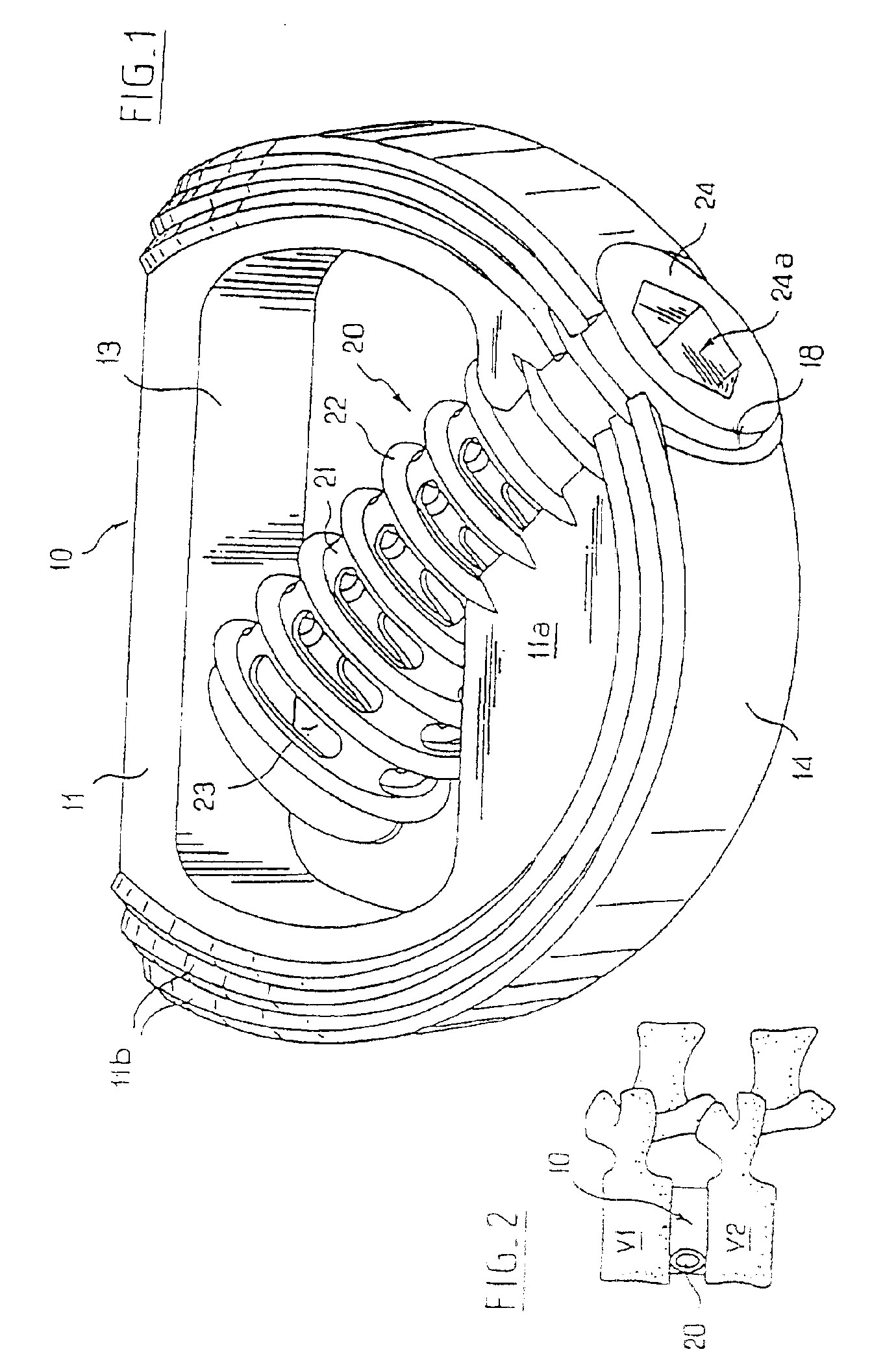
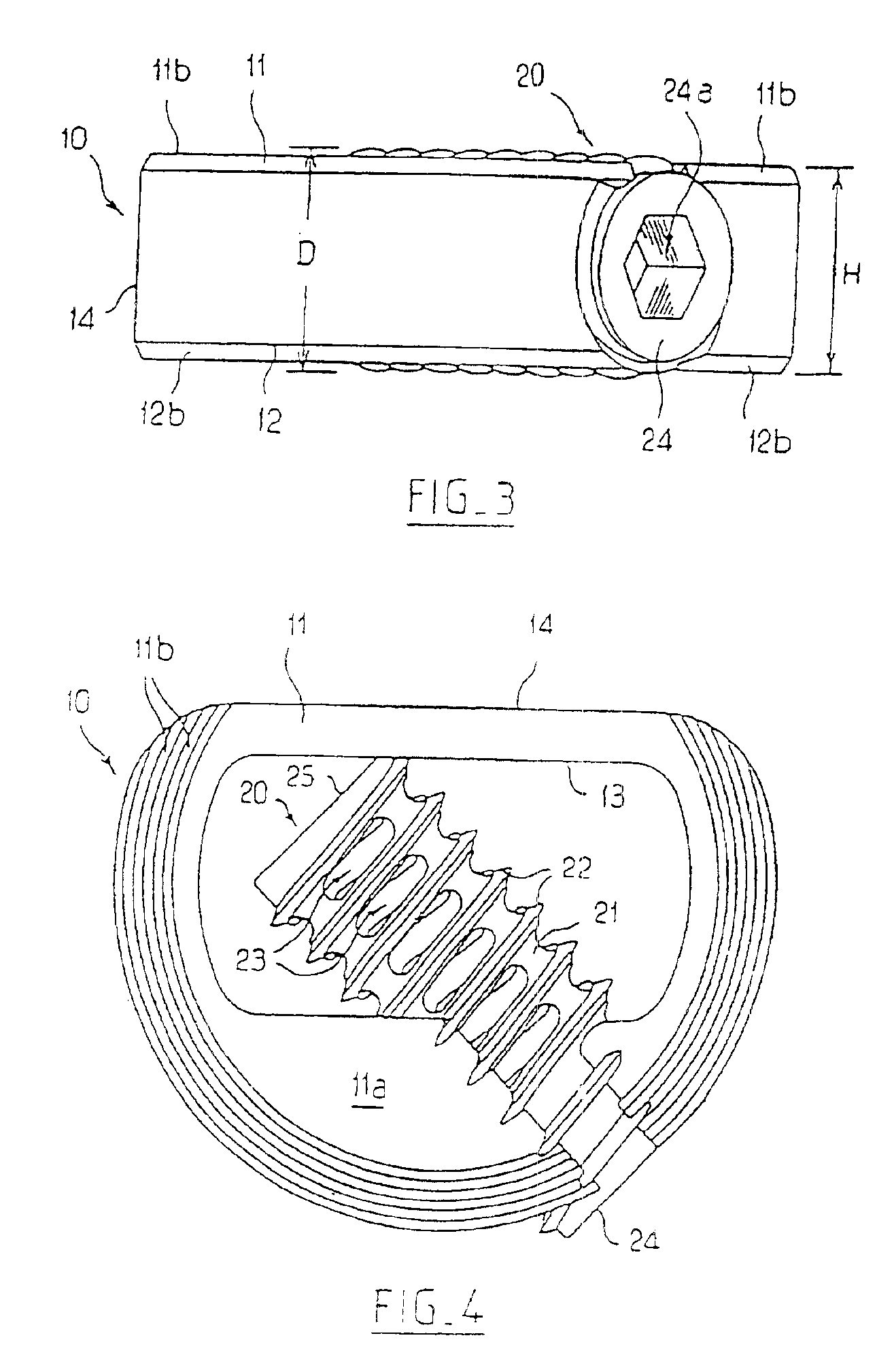
It will first be noted that the body 10, which has the same contour as in the case of FIGS. 1 to 8, has a wall of essentially constant thickness over its whole periphery.

Instead of the tapped-through orifice 18 in the first embodiment, this body includes a smooth-through orifice 19.

Moreover, a cylindrical rod 16 provided with a thread 16a extends along the axis of the orifice 19 starting from the opposite region of the body 10, situated. essentially at the transition between its circular contour and straight contour parts.

In addition, the member 20, which has substantially the same external contour as in the case of the first embodiment, is solid, except for a central bore 28 which opens out on its rear face and in ...


PUM

PropertyMeasurementUnit
Fractionaaaaaaaaaa
Angleaaaaaaaaaa

Abstract

A spinal implant includes a hollow body having a distal end, a proximal end, and a pair of lateral walls extending from the distal end to the proximal end, the lateral walls having a concave-shaped cross-section with curved exterior surfaces and having concave, non-threaded interior surfaces for defining an at least partially cylindrical internal space between the lateral walls. The spinal implant also includes an anchoring member having bone anchoring projections including a screw thread on an exterior surface thereof, wherein at least one of the lateral walls adjacent the proximal end of the hollow body includes a reentrant thread adapted to cooperate with the screw thread of the anchoring member when the anchoring element is rotated for enabling the anchoring member to be screwed into the internal space of the hollow body.

Description

BACKGROUND OF THE INVENTIONThe present invention relates generally to intersomatic implants which can be used in the surgical treatment of the spine.A great many intersomatic implants are already known.These include, in particular, implants having a more or less complex structure, made up of several parts, particularly to give them certain deformability characteristics. These known implants have the disadvantage that they are more expensive and difficult to manufacture, and that they are more awkward to fit. They can also suffer from a problem of long-term reliability.Implants are also known which, in order in particular to overcome all or some of the above disadvantages, being in the form or on-piece hollow bodies, or cages, provided with roughened areas on their upper and rear faces in order to ensure good, initial immobilization relative to the overlying and underlying vertebral plateaus, their hollow character permitting bone to grow through them and, eventually, immobilize them...

Claims


Application Information

Patent Timeline
IPC IPC(8): A61B17/86A61B17/68A61F2/44A61B17/88A61F2/30A61F2/00A61F2/28A61F2/46
CPCA61B17/86A61F2/442A61F2/4455A61F2/446A61F2/447A61B17/861A61F2310/00796A61B17/8625A61B17/864A61B17/8645A61B17/8875A61F2/30744A61F2/30767A61F2/4611A61F2002/2835A61F2002/30118A61F2002/30131A61F2002/30143A61F2002/30169A61F2002/30187A61F2002/30217A61F2002/30224A61F2002/30233A61F2002/30235A61F2002/30271A61F2002/30354A61F2002/30364A61F2002/30367A61F2002/30373A61F2002/30405A61F2002/305A61F2002/30616A61F2002/30772A61F2002/30774A61F2002/30777A61F2002/30797A61F2002/30848A61F2002/3085A61F2002/30879A61F2002/30904A61F2002/4475A61F2002/448A61F2220/0025A61F2220/0033A61F2230/0006A61F2230/0013A61F2230/0017A61F2230/0034A61F2230/0047A61F2230/0067A61F2230/0069A61F2230/0082A61F2310/00017A61F2310/00023A61F2002/30261A61F2002/30593A61F2002/30845
Inventor CROZET, YVES
Owner STRYKER EURO OPERATIONS HLDG LLC
Why Eureka
Try Eureka