
System and method for percutaneously administering reduced pressure treatment using a flowable manifold

a flowable manifold and reduced pressure technology, applied in the field of tissue growth promotion system or system of tissue growth promotion, can solve the problems of pain to patients during foam removal, reduced pressure therapy has not been used in connection with healing bone defects or promoting bone growth, and reduced pressure therapy has not been used in connection with promoting bone growth and healing. , the effect of reducing pressur

Active Publication Date: 2007-09-20
KCI LICENSING INC
View PDF102 Cites 82 Cited by
  • Summary
  • Abstract
  • Description
  • Claims
  • Application Information

AI Technical Summary

Benefits of technology

[0006]Reduced pressure therapy is typically applied to non-healing, open wounds. In some cases, the tissues being healed are subcutaneous, and in other cases, the tissues are located within or on dermal tissue. Traditionally, reduced pressure therapy has primarily been applied to soft tissues. Reduced pressure therapy has not typically been used to treat closed, deep-tissue wounds because of the difficulty of access presented by such wounds. Additionally, reduced pressure therapy has not been used in connection with healing bone defects or promoting bone growth, primarily due to access problems. Surgically exposing a bone to apply reduced pressure therapy may create more problems than it solves. Finally, devices and systems for applying reduced pressure therapy have advanced little beyond the open-cell foam pieces that are manually shaped to fit a wound site and then removed following a period of reduced pressure therapy.

Problems solved by technology

Significant tissue in-growth can cause pain to patients during removal of the foam.
Reduced pressure therapy has not typically been used to treat closed, deep-tissue wounds because of the difficulty of access presented by such wounds.
Additionally, reduced pressure therapy has not been used in connection with healing bone defects or promoting bone growth, primarily due to access problems.
Surgically exposing a bone to apply reduced pressure therapy may create more problems than it solves.

Method used


Image

  • System and method for percutaneously administering reduced pressure treatment using a flowable manifold
  • System and method for percutaneously administering reduced pressure treatment using a flowable manifold
  • System and method for percutaneously administering reduced pressure treatment using a flowable manifold

Examples


Embodiment Construction

[0060]In the following detailed description of the preferred embodiments, reference is made to the accompanying drawings that form a part hereof, and in which is shown by way of illustration specific preferred embodiments in which the invention may be practiced. These embodiments are described in sufficient detail to enable those skilled in the art to practice the invention, and it is understood that other embodiments may be utilized and that logical structural, mechanical, electrical, and chemical changes may be made without departing from the spirit or scope of the invention. To avoid detail not necessary to enable those skilled in the art to practice the invention, the description may omit certain information known to those skilled in the art. The following detailed description is, therefore, not to be taken in a limiting sense, and the scope of the present invention is defined only by the appended claims.

[0061]As used herein, the term “elastomeric” means having the properties of...


PUM

PropertyMeasurementUnit
Temperatureaaaaaaaaaa
Pressureaaaaaaaaaa
Flow rateaaaaaaaaaa

Abstract

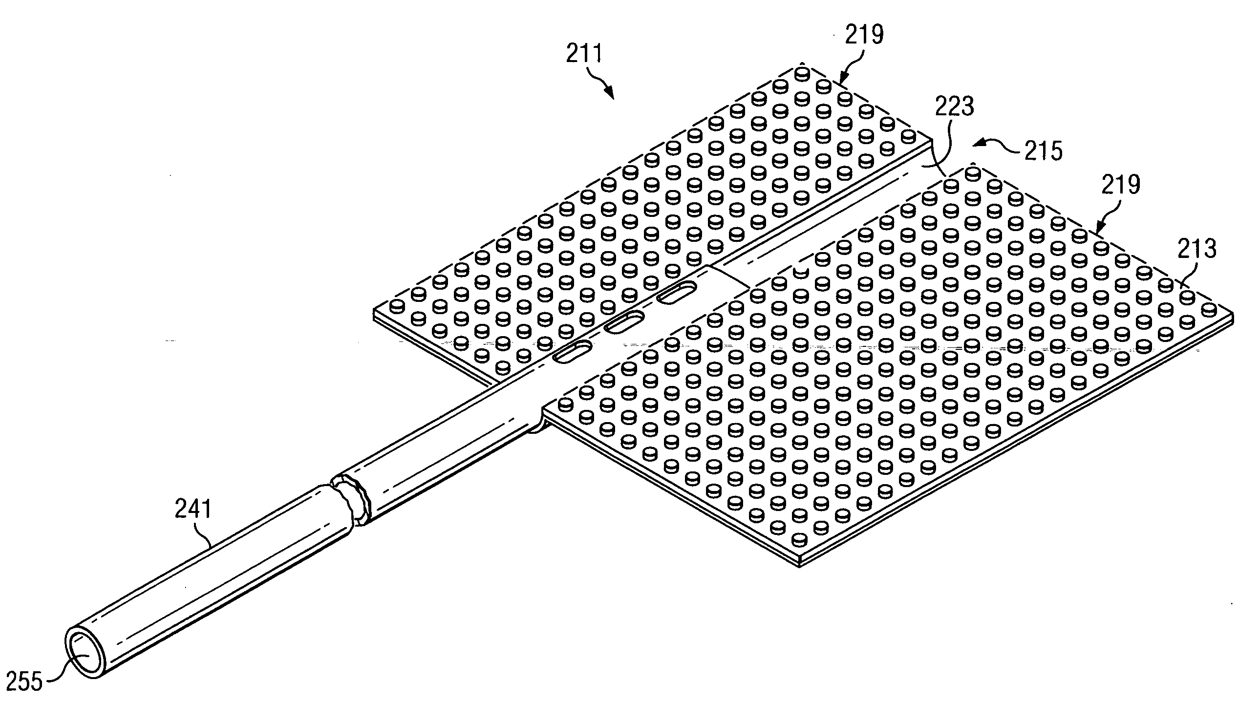
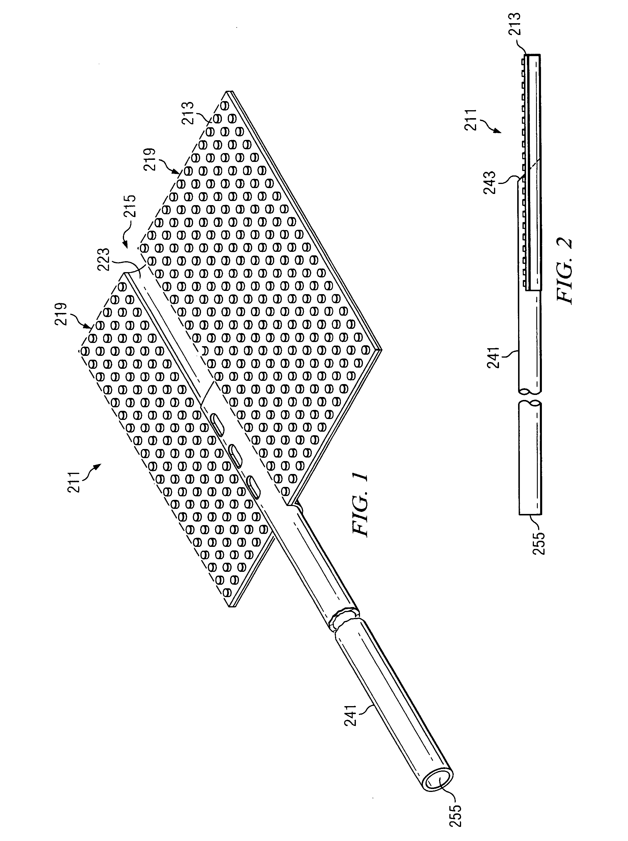
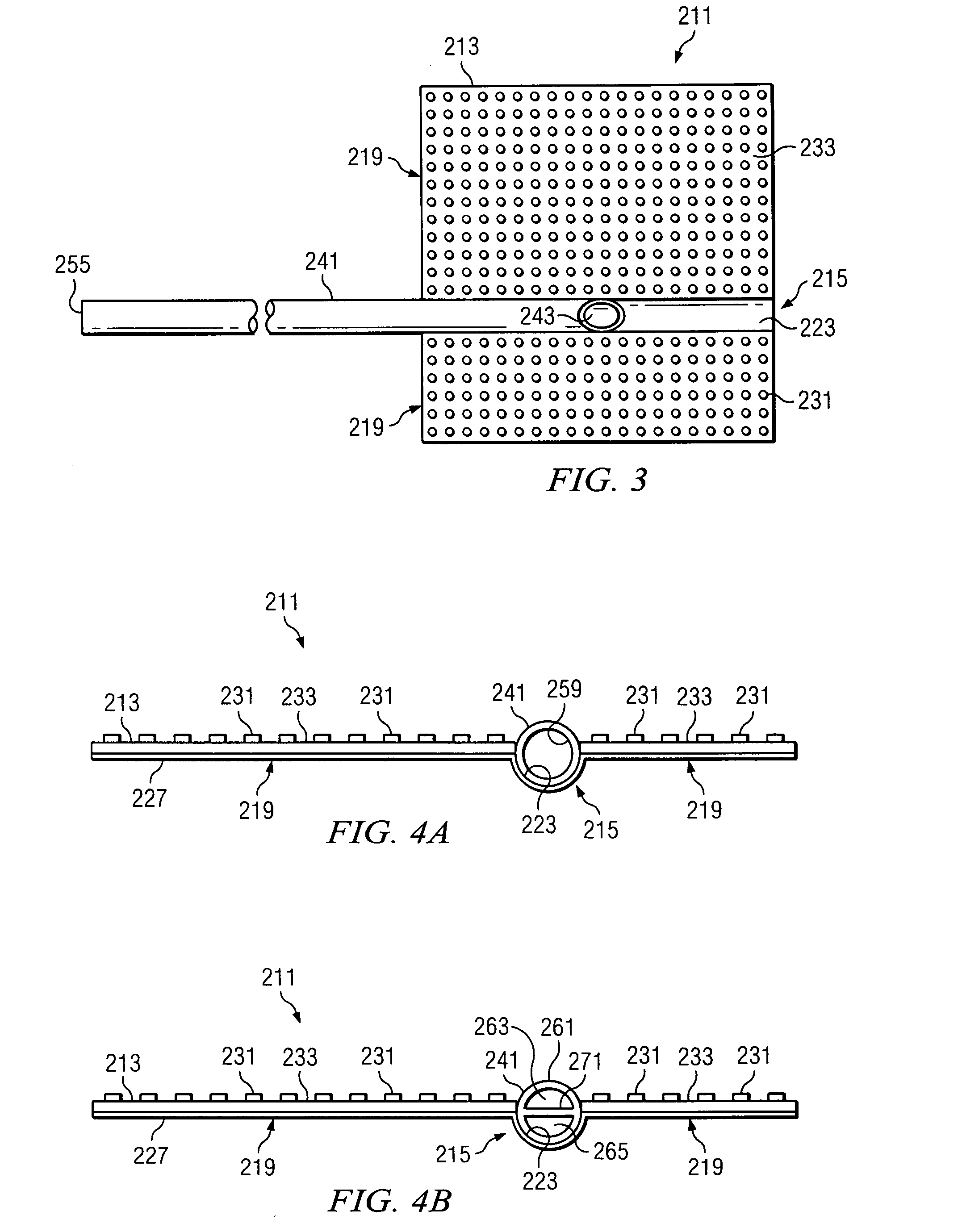
A reduced pressure delivery system for applying a reduced pressure to a tissue site includes a manifold delivery tube having a passageway and a distal end, the distal end configured to be percutaneously inserted and placed adjacent the tissue site. A flowable material is provided and is percutaneously deliverable through the manifold delivery tube to the tissue site. The flowable material is capable of filling a void adjacent the tissue site to create a manifold having a plurality of flow channels in fluid communication with the tissue site. A reduced pressure delivery tube is provided that is capable of fluid communication with the flow channels of the manifold.

Description

CROSS REFERENCE TO RELATED APPLICATIONS[0001]This application claims the benefit of U.S. Provisional Application No. 60 / 782,171, filed Mar. 14, 2006, which is hereby incorporated by reference.BACKGROUND OF THE INVENTION[0002]1. Field of the Invention[0003]This invention relates generally to a system or method of promoting tissue growth and more specifically a system for applying reduced pressure tissue treatment to a tissue site.[0004]2. Description of Related Art[0005]Reduced pressure therapy is increasingly used to promote wound healing in soft tissue wounds that are slow to heal or non-healing without reduced pressure therapy. Typically, reduced pressure is applied to the wound site through an open-cell foam that serves as a manifold to distribute the reduced pressure. The open-cell foam is sized to fit the existing wound, placed into contact with the wound, and then periodically replaced with smaller pieces of foam as the wound begins to heal and become smaller. Frequent replace...

Claims


Application Information

Patent Timeline
IPC IPC(8): A61F2/00A61F2/958
CPCA61B17/1355A61F13/00068A61B17/88A61F2/30767A61F2/36A61F2/3662A61F2002/30677A61F2002/30785A61F2002/30787A61F2002/30968A61F2002/3611A61F2002/3625A61F2002/368A61F2002/3694A61F2310/00395A61F2310/00592A61F2310/00928A61M1/0088A61M27/00A61M37/00A61F2/0077A61F2002/0086A61L31/146A61M1/0084A61M5/14A61M1/0092A61F13/0216A61M1/0023A61M1/0037A61B17/80A61M1/964A61M1/916A61M1/85A61M1/96A61M1/915A61M1/92A61F5/00A61K9/14A61K9/70A61F2002/3068A61B17/12168A61B17/12181A61B17/1219A61B17/12186A61M2025/1086A61B17/12195A61M1/75A61F13/05A61H9/005A61H2201/0103
Inventor JOHNSON, ROYCE W.AMBROSIO, ARCHEL A.SWAIN, LARRY D.PAYNE, JOANNA
Owner KCI LICENSING INC
Learn More