Cryotherapy system

a cryotherapy and system technology, applied in the field of cryotherapy, can solve the problems of increasing the difficulty of pc monitoring with standard ultrasound, not adequately challenging the current popularity enjoyed by cryotherapy systems, and reducing the patient's comfort of cryotherapy, so as to reduce the pressure of liquid

Active Publication Date: 2006-08-01
ADAGIO MEDICAL
View PDF78 Cites 257 Cited by
  • Summary
  • Abstract
  • Description
  • Claims
  • Application Information

AI Technical Summary

Benefits of technology

[0011]In some embodiments, the self-contained fluid system is an open-loop system, while in other embodiments it is a closed-loop system. Furthermore, in different embodiments, the cryogenic fluid may be a gas or may be a liquid. In one embodiment where it is a gas, each cryoprobe further has a heat exchanger disposed within the shaft in thermal communication with the conduits of the cryoprobe. In addition, each cryoprobe may include a Joule-Thomson port disposed in the distal end of the shaft in thermal communication with the heat exchanger, with the computer processor additionally controlling operation of each of the Joule-Thomson ports. In one embodiment where the cryogenic fluid is a liquid, the computer processor controls the compressor and flow-control metering valves to provide an initial flow of the liquid under physical conditions near a critical point of a liquid-vapor system for the liquid. Vapor lock associated with freezing of the cryoprobes is thereby avoided. The computer processor may subsequently control the compressor and flow-control metering valves to reduce a pressure of the liquid in the cryoprobes, allowing colder liquid temperatures to be maintained without vapor lock after the initial flow is established. In one instance, a source of warmed gas may be flowed through the conduits as part of an active-thaw procedure.

Problems solved by technology

Without a relatively small, self-contained, easy-to-use cryosystem employing lower priced probes (i.e., currently each Endocare probe costs ˜$400–1500), the patient benefits of cryotherapy (i.e., lower pain, clear imaging of ablation zone and minimal scarring) will not adequately challenge the current popularity enjoyed by heat-based systems.
PC monitoring is more difficult with standard ultrasound since it visualizes the treatment site from limited external positions.
The Cryomedical Sciences efforts attempted to combat the flow difficulties encountered by liquid nitrogen (LN2) in smaller probes (e.g., ≦3 mm) but required a highly complex system using large LN2 volumes.
While the Cryogen patents referred to a closed-loop gas system, no thermodynamic optimization was described to reduce engineering complexity.
Therefore, companies with units which use large flow rates, or amounts of gas, to produce maximal freeze capacity per probe generally acknowledge the desire for an open system since the required compressors for such closed systems would become too large, expensive and unwieldy for portable use.
In addition, the lack of optimized cryogenic design and probe configuration to produce the greatest freeze power for the minimal gas flow configuration prevents the design of smaller (i.e., <1.5 mm) probe diameters.
These devices take advantage of the fact that non-ideal gases, when rapidly expanded, become extremely cold.
A deficiency to broad adoption of gas-based systems by physicians and hospitals appears to be their lack of efficient self-contained systems.

Method used


Image

  • Cryotherapy system
  • Cryotherapy system
  • Cryotherapy system

Examples


Embodiment Construction

1. Introduction: Thermodynamics of Cooling Cycles

[0028]As an initial matter, we analyze and compare two methods of cryogenic refrigeration that are currently being used in various cryotherapy tools: a) isoenthalpic expansion cooling (the Joule-Thomson process) from a high-pressure gas (Ar or N2), and b) direct injection of a liquid coolant (liquid N2, hereafter LN2) into the tip of a cryoprobe.

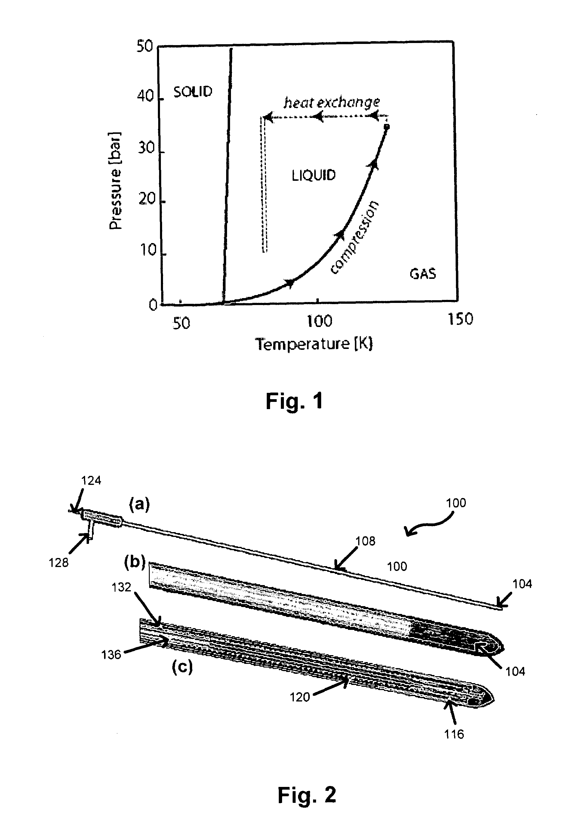
[0029]a. Joule-Thomson (JT) Cooling

[0030]This refrigeration technique uses a high pressure gas supply (≈6000 psi), a JT expansion jet that cools the tip of the probe, and a small heat exchanger that is mounted inside the cryoprobe. Assuming ideal (perfect) heat exchange between the gas streams, the maximum cooling power of the JT cooling is equal to 1.86 kJ / mol for Ar gas at its boiling temperature (and one atmosphere pressure) TAr=87 K. If nitrogen gas is used, the maximum cooling power is about 1.6 times less i.e. 1.15 kJ / mol.

[0031]The main disadvantage of this method is very large gas consu...


PUM


Abstract

A cryotherapy system is provided with multiple cryoprobes, each of which has a shaft with a closed distal end adapted for insertion into a body and conduits for flowing a cryogenic fluid through the shaft to reduce a temperature of the distal end. A source is provided for the cryogenic fluid, and flow-control metering valves are provided in fluid communication with the conduits and source of the cryogenic fluid. A compressor is provided in fluid communication with the conduits of the cryoprobes to define a self-contained fluid system. The flow-control metering valves and the compressor are controlled by a computer processor to provide the desired flows of the cryogenic fluid through the conduits of the self-contained fluid system.

Description

CROSS-REFERENCES TO RELATED APPLICATIONS[0001]This application is a nonprovisional application of, and claims the benefit of the filing date of, U.S. Prov. Pat. Appl. No. 60 / 440,662, entitled “CRYOSURGICAL SYSTEM,” filed Jan. 15, 2003 by Peter Littrup et al., the entire disclosure of which is incorporated herein by reference for all purposes, including the appendices.[0002]This application is related to concurrently filed, commonly assigned U.S. patent application Ser. No. 10 / 757,768, entitled “CRYOTHERAPY PROBE,” by Peter Littrup et al. which is a nonprovisional application of U.S. Prov. Pat. AppI. No. 60 / 440,541, entitled “CRYOSURGICAL PROBE,” filed Jan. 15, 2003 by Peter Littrup et al., the entire disclosures of both of which are incorporated herein by reference for all purposes, including the appendices.BACKGROUND OF THE INVENTION[0003]This invention relates to generally to cryotherapy. More specifically, this application relates to image-guided control of cryoprobes and cryocoo...

Claims


Application Information

Patent Timeline
Patent Type & Authority Patents(United States)
IPC IPC(8): A61B18/02A61F7/12F25D3/10
CPCA61B18/02F25D3/10A61B18/0218A61B2018/00017A61B2018/0262A61B2018/0293A61B2018/00023
Inventor LITTRUP, PETER J.BABKIN, ALEXEI V.DUNCAN, ROBERTBOLDAROV, SERGEI
Owner ADAGIO MEDICAL
Why Eureka
Try Eureka