Systems, devices and methods for treatment of intervertebral disorders

a technology for intervertebral discs and devices, applied in the direction of spinal implants, prostheses, coatings, etc., can solve the problems of increasing disc height and unfavorable permanent pressurization implants, and achieve the effects of reducing hydrostatic tissue pressure, increasing disc height, and increasing biomechanical stability

Inactive Publication Date: 2006-07-06
RGT UNIV OF CALIFORNIA
View PDF7 Cites 253 Cited by
  • Summary
  • Abstract
  • Description
  • Claims
  • Application Information

AI Technical Summary

Benefits of technology

[0015] The present invention comprises an implant and minimally invasive method of treating degenerated discs which can repair and regenerate the disc. More particularly, the present invention comprises a bioactive / biodegradable nucleus implant and method of use. The implant is inflated inside the nucleus space after the degenerated nucleus has been removed to re-pressurize the nuclear space within the intervertebral disc. Nuclear pressure produces tension in the annular ligament that increases biomechanical stability and diminishes hydrostatic tissue pressure that can stimulate fibro-chondrocytes to produce inflammatory factors. The device will also increase disc height, separate the vertebral bodies and open the spinal foramina.
[0017] One of the main difficulties in repairing the degenerated disc is increasing the disc height. The disc and surrounding tissues such as ligaments provide a great deal of resistance to disc heightening. For this reason it is unlikely that placing a hydrogel alone into the nuclear space will be able to generate enough swelling pressure to regain significant disc height. The present invention, however, addresses this problem by allowing initial high pressures to be generated when the implant is inflated in the nuclear space. The initial high pressure is sufficient to initiate the restoration of the original disc height. This initial boost in disc height facilitates the later regeneration stages of this treatment.
[0026] In an alternative embodiment, the stent is configured to be expanded around an inflatable membrane. In this case, the inflated membrane supports intervertebral compression, while the stent prevents membrane lateral expansion or lateral migration.
[0027] Yet another aspect of the invention is a method for facilitating regeneration of the intervertebral disc, comprising inserting a collapsed stent into a nuclear cavity in the nucleus pulposus tissue, and expanding the stent to support a portion of intervertebral compression loads and thereby facilitate nuclear regeneration.
[0037] Yet a further aspect of the invention is an implant for repairing an intervertebral disc disposed between opposing vertebral endplates of adjacent vertebrae. The implant has membrane having upper and lower walls configured to engage said vertebral endplates, and reinforced peripheral walls joining the upper and lower walls. The peripherally reinforced walls may have a variety of beneficial attributes, including prevent bulging of the membrane a result of compressive forces imposed on said membrane from the vertebral endplates, increasing fatigue resistance, or providing stiffness in an under inflation condition. Additionally, the reinforced peripheral wall may create a nonlinearity in overall device stiffness during bending or compression to improve overall intervertebral stability

Problems solved by technology

One of the main difficulties in repairing the degenerated disc is increasing the disc height.
In the long term, having a permanent pressurized implant is not likely to be ideal because it may not be able to mimic the essential biomechanical properties of the normal disc.

Method used


Image

  • Systems, devices and methods for treatment of intervertebral disorders
  • Systems, devices and methods for treatment of intervertebral disorders
  • Systems, devices and methods for treatment of intervertebral disorders

Examples


example 1

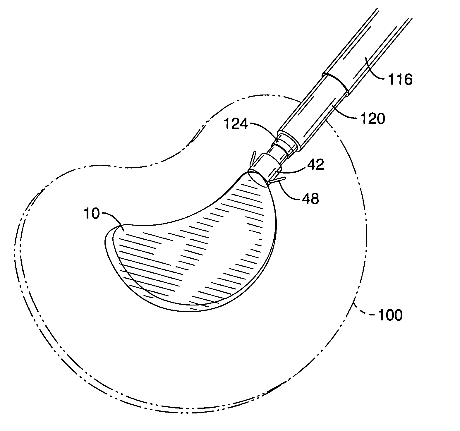
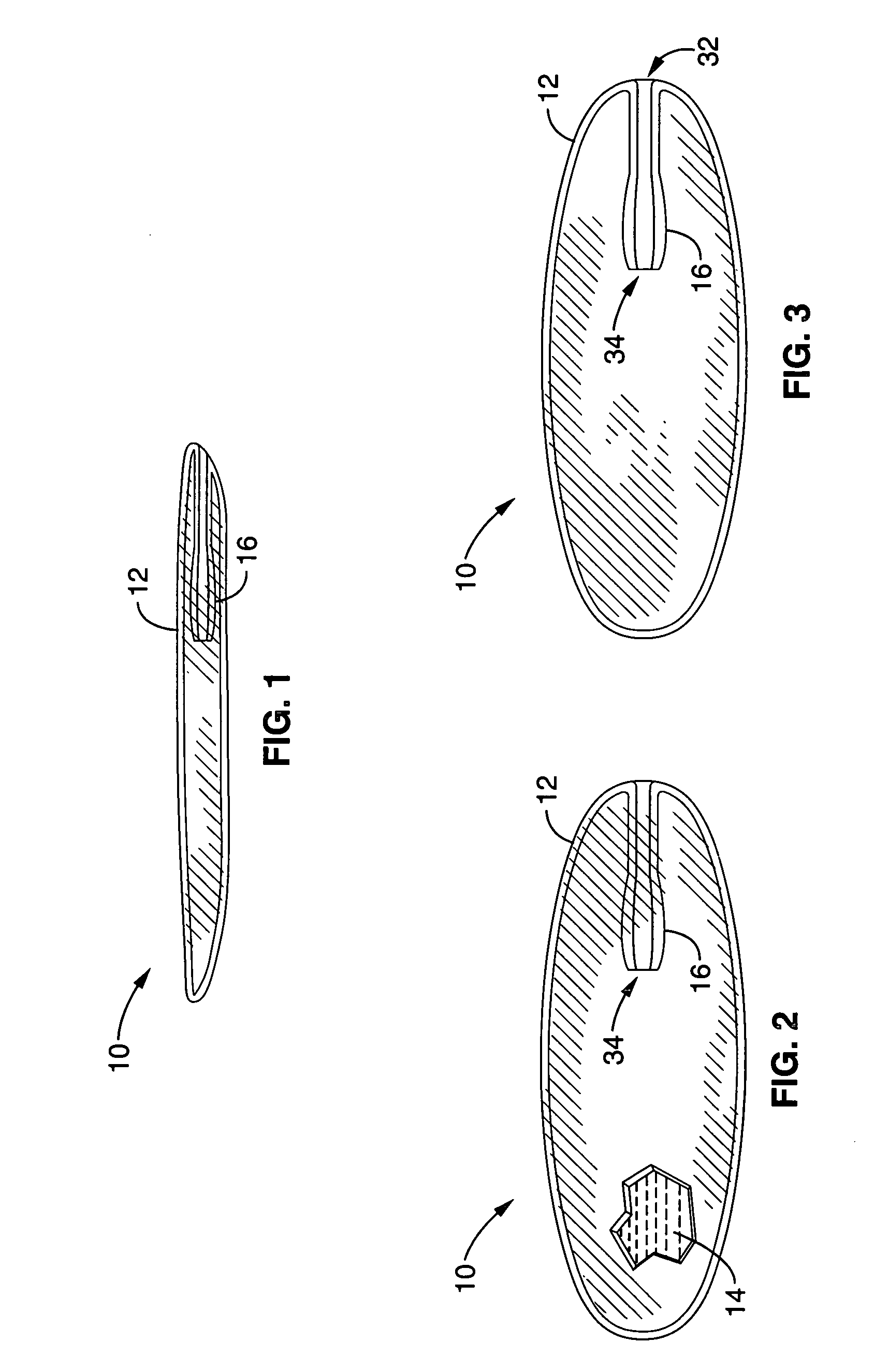
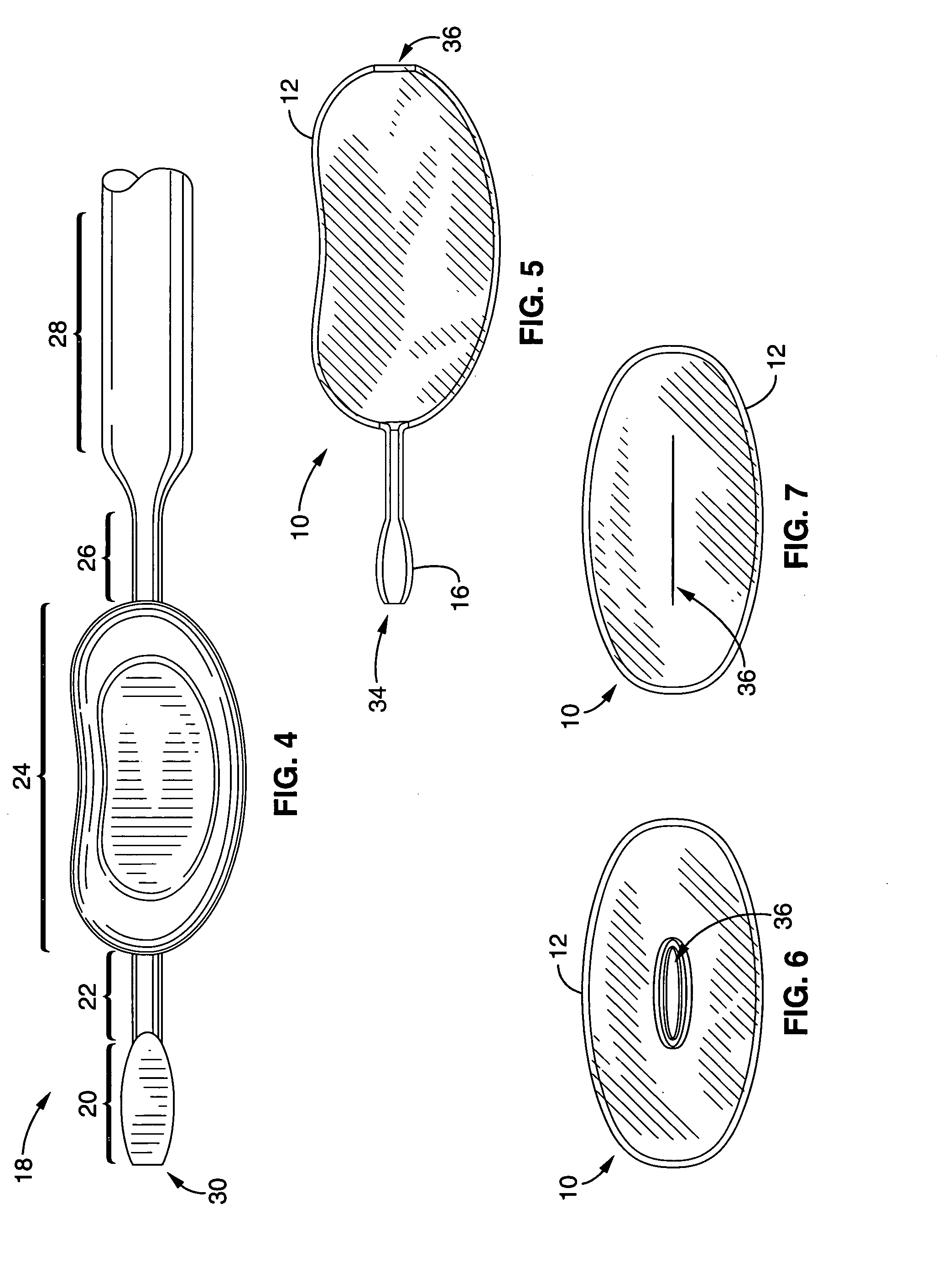
[0117] Prototype implant shells were fabricated by Apex Biomedical (San Diego, Calif.). The fabrication process included dip molding using a custom-fabricated mandrel. The mandrel was dipped so that the elastomer thickness was between 5 and 7 mils (0.13-0.17 mm). After dipping, the implant was removed from the mandrel, inverted (so that the stem was inside the implant) and heat-sealed at the open end. This process resulted in a prototype that could be filled with the PEG gel, which when cross-linked could not exit through the implant stem. The stem effectively sealed the implant by functioning as a “flapper valve”. This means that by being placed within the implant, internal pressures (that might serve to extrude the gel) compress and seal the stem, creating a barrier to extrusion. This sealing mechanism was verified by in vitro testing.

example 2

[0118] Elastomer bags filled with PEG were compressed to failure between two parallel platens. The implants failed at the heat seal at approximately 250 Newtons force. These experiments demonstrated that under hyper-pressurization, the failure mechanism was rupture at the sealed edge, rather than extrusion of gel through the insertion stem. When the device is placed within the intervertebral disc, support by the annulus and vertebral body results in a significantly increased failure load and altered construct failure mechanism.

example 3

[0119] Ex vivo mechanical testing were performed with human cadaveric spines to characterize the performance of the device under expected extreme in vivo conditions. We conducted a series of experiments that consisted of placing the device in human cadaveric discs using the developed surgical protocols and then testing the construct to failure under compressive loading. The objective of these experiments was to characterize the failure load and failure mechanism. The target failure load was to exceed five times body weight (anticipated extremes of in vivo loading). Importantly, the failure mode was to be endplate fracture and extrusion of the implant into the adjacent vertebra. This is the mode of disc injury in healthy spines. We did not want the construct to fail by extrusion through the annulus, particularly through the insertion hole, since this would place the hydrogel in close proximity to sensitive neural structures.

[0120] Load-to-failure experiments demonstrated that the im...


PUM

PropertyMeasurementUnit
water contentaaaaaaaaaa
heightaaaaaaaaaa
heightaaaaaaaaaa

Abstract

A bioactive / biodegradable nucleus implant for repairing degenerated intervertebral discs that is inflated inside the nucleus space after the degenerated nucleus has been removed to re-pressurize the nuclear space within the intervertebral disc. The implant is inflated with a high molecular weight fluid, gel or combination of fluid and elastomer, preferably an under-hydrated HA hydrogel / growth factor mixture with or without host cells. The implant includes an internal, integral, self-sealing valve that allows one-way filling of the implant after it is placed within the disc, and is made from a material that allows fibrous in growth thereby stabilizing the implant. A variety of substances can be incorporated into the implant to promote healing, prevent infection, or arrest pain.

Description

CROSS-REFERENCE TO RELATED APPLICATIONS [0001] This application claims priority from U.S. provisional application Ser. No. 60 / 632,396 filed on Dec. 1, 2004, incorporated herein by reference in its entirety.STATEMENT REGARDING FEDERALLY SPONSORED RESEARCH OR DEVELOPMENT [0002] Not Applicable INCORPORATION-BY-REFERENCE OF MATERIAL SUBMITTED ON A COMPACT DISC [0003] Not Applicable NOTICE OF MATERIAL SUBJECT TO COPYRIGHT PROTECTION [0004] A portion of the material in this patent document is subject to copyright protection under the copyright laws of the United States and of other countries. The owner of the copyright rights has no objection to the facsimile reproduction by anyone of the patent document or the patent disclosure, as it appears in the United States Patent and Trademark Office publicly available file or records, but otherwise reserves all copyright rights whatsoever. The copyright owner does not hereby waive any of its rights to have this patent document maintained in secre...

Claims


Application Information

Patent Timeline
Patent Type & Authority Applications(United States)
IPC IPC(8): A61F2/44
CPCA61B17/0401A61B2017/044A61F2/30771A61F2/3094A61F2/30965A61F2/441A61F2/442A61F2/4611A61F2002/009A61F2002/30014A61F2002/30023A61F2002/30062A61F2002/30075A61F2002/30092A61F2002/302A61F2002/30324A61F2002/30565A61F2002/30578A61F2002/30579A61F2002/30586A61F2002/30601A61F2002/30677A61F2002/3092A61F2002/30932A61F2002/30971A61F2002/4435A61F2002/444A61F2002/4627A61F2002/4629A61F2210/0004A61F2210/0014A61F2210/0061A61F2230/0065A61F2250/0018A61F2250/0034A61F2250/0036A61F2310/00976A61F2/30907
Inventor LOTZ, JEFFREY C.BRADFORD, DAVID S.
Owner RGT UNIV OF CALIFORNIA
Why Eureka
Try Eureka