Surgical instrument for handling an implant

a surgical instrument and implant technology, applied in the field of inserting instruments, can solve the problems of shock on the implant, high risk, damage to the joint surface,

a surgical instrument and implant technology, applied in the field of inserting instruments, can solve the problems of shock on the implant, high risk, damage to the joint surface,

US7549995B2Inactive Publication Date: 2009-06-23AESCULAP AG

Image

  • Surgical instrument for handling an implant
  • Surgical instrument for handling an implant
  • Surgical instrument for handling an implant

Examples


Embodiment Construction

[0022]Although the invention is illustrated and described herein with reference to specific embodiments, the invention is not intended to be limited to the details shown. Rather, various modifications may be made in the details within the scope and range of equivalents of the claims and without departing from the invention.

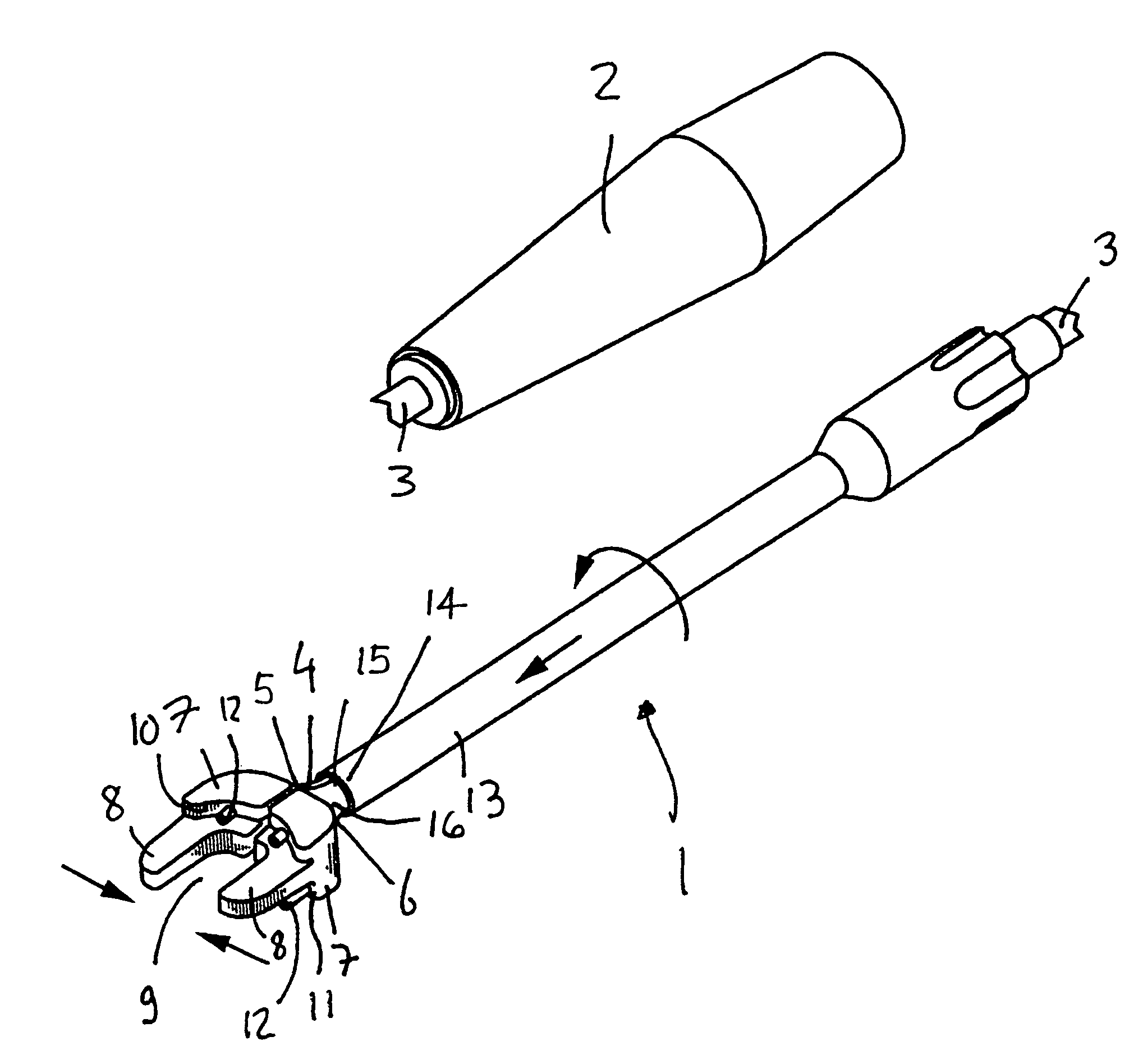
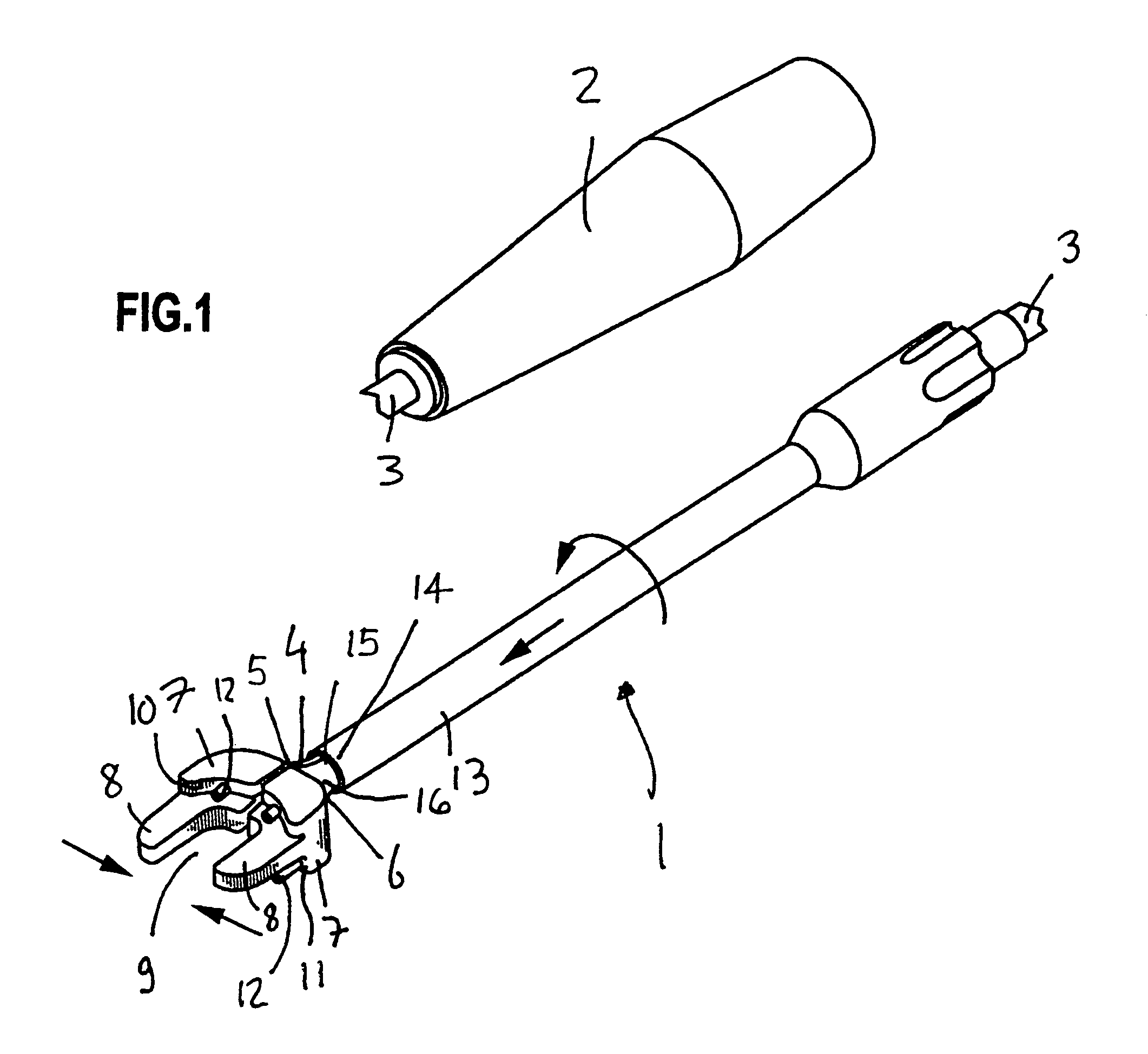
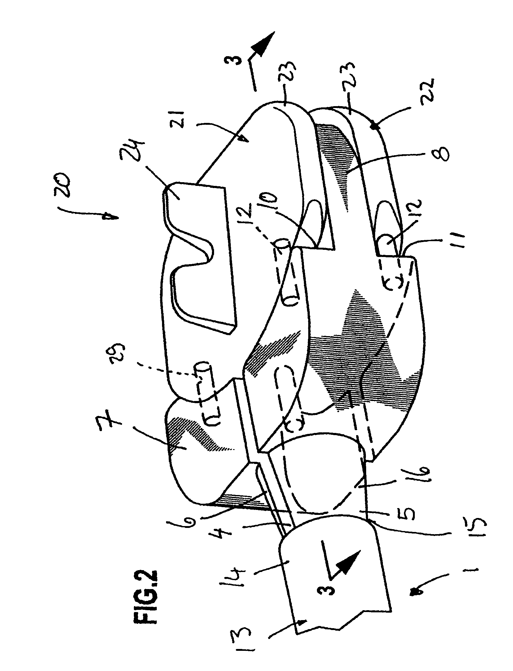
[0023]The surgical instrument 1 shown in the drawings comprises a handle 2 with a bar 3 held thereon, which is divided at its end located opposite the handle 2 by a longitudinal slot 4 into two parallel arms 5, 6, which can be elastically pivoted against each other or apart from one another. The two arms 5, 6 have the same design, and only one part will therefore be described in detail below. At its end, the arm carries a clamping jaw 7, which may be made in one piece with the arm and is broader and higher than the arm. A substantially plate-shaped spacer member 8 is arranged at each clamping jaw 7, the spacer member 8 extending in the longitudinal direction of th...


PUM


Abstract

An implant has two parts, each of which includes a joint surface facing the other part, wherein the joint surfaces are in contact with one another in an implanted state and permit pivoting of the two parts in relation to one another. An instrument for handling the implant includes a holding element for detachably connecting the instrument with each of the two parts of the implant. The instrument further includes a spacer element extending between the parts of the implant when the parts are connected with the instrument and maintaining a distance between the parts, thereby preventing the joint surfaces of the two parts of the implant from contacting each other.

Description

[0001]This application is related to and claims the benefit of German Utility Model No. 203 10 433.1 entitled Surgical Instrument for Handling an Implant issued on Sep. 4, 2003, and German Patent Application No. 103 30 699.4-35 filed Jul. 8, 2003.FIELD OF THE INVENTION[0002]The present invention pertains to an inserting instrument for an intervertebral disk prosthesis. An intervertebral disk prosthesis can be inserted with this inserting instrument such that the bearing components are protected from impact pulses that may occur during the implantation.BACKGROUND OF THE INVENTION[0003]A surgical instrument for handling an implant is known, for example, from WO 01 / 19295 A1, and is used to pick up an intervertebral implant and then introduce it into the intervertebral space between two vertebral bodies. With the prior-art instrument, the two parts of the implant are introduced into the intervertebral space in such a way that they are closely in contact with one another and are then rem...

Claims


Application Information

Patent Timeline
23 Jun 2009
Publication
US7549995B2
IPC
A61B17/58; A61B17/28; A61B19/00; A61F2/00; A61F2/30; A61F2/44; A61F2/46
CPC
A61F2/4425; A61F2/4611; A61F2002/4622; A61F2002/4623; A61F2002/4627; A61F2002/4628; A61F2002/4681; A61F2220/0025
Inventors
SCHULTZ, ROBERT