Tibial tuberosity advancement implant

Inactive Publication Date: 2010-03-25
MWI VETERINARY SUPPLY
View PDF5 Cites 83 Cited by
  • Summary
  • Abstract
  • Description
  • Claims
  • Application Information

AI Technical Summary

Benefits of technology

[0008]It is a further object of this invention to provide such an implant which is strong.
[0009]It is a further object of this invention to provide such an implant which enables bone growth.
[0010]It is a further object of this invention to provide such an implant which is biocompatible and light weight.
[0011]It is a further object of this invention to provi

Problems solved by technology

Presently, the procedure is complex and expensive due to the need for the implanted cage, the tens

Method used


Image

  • Tibial tuberosity advancement implant
  • Tibial tuberosity advancement implant
  • Tibial tuberosity advancement implant

Examples


Embodiment Construction

[0032]Aside from the preferred embodiment or embodiments disclosed below, this invention is capable of other embodiments and of being practiced or being carried out in various ways. Thus, it is to be understood that the invention is not limited in its application to the details of construction and the arrangements of components set forth in the following description or illustrated in the drawings. If only one embodiment is described herein, the claims hereof are not to be limited to that embodiment. Moreover, the claims hereof are not to be read restrictively unless there is clear and convincing evidence manifesting a certain exclusion, restriction, or disclaimer.

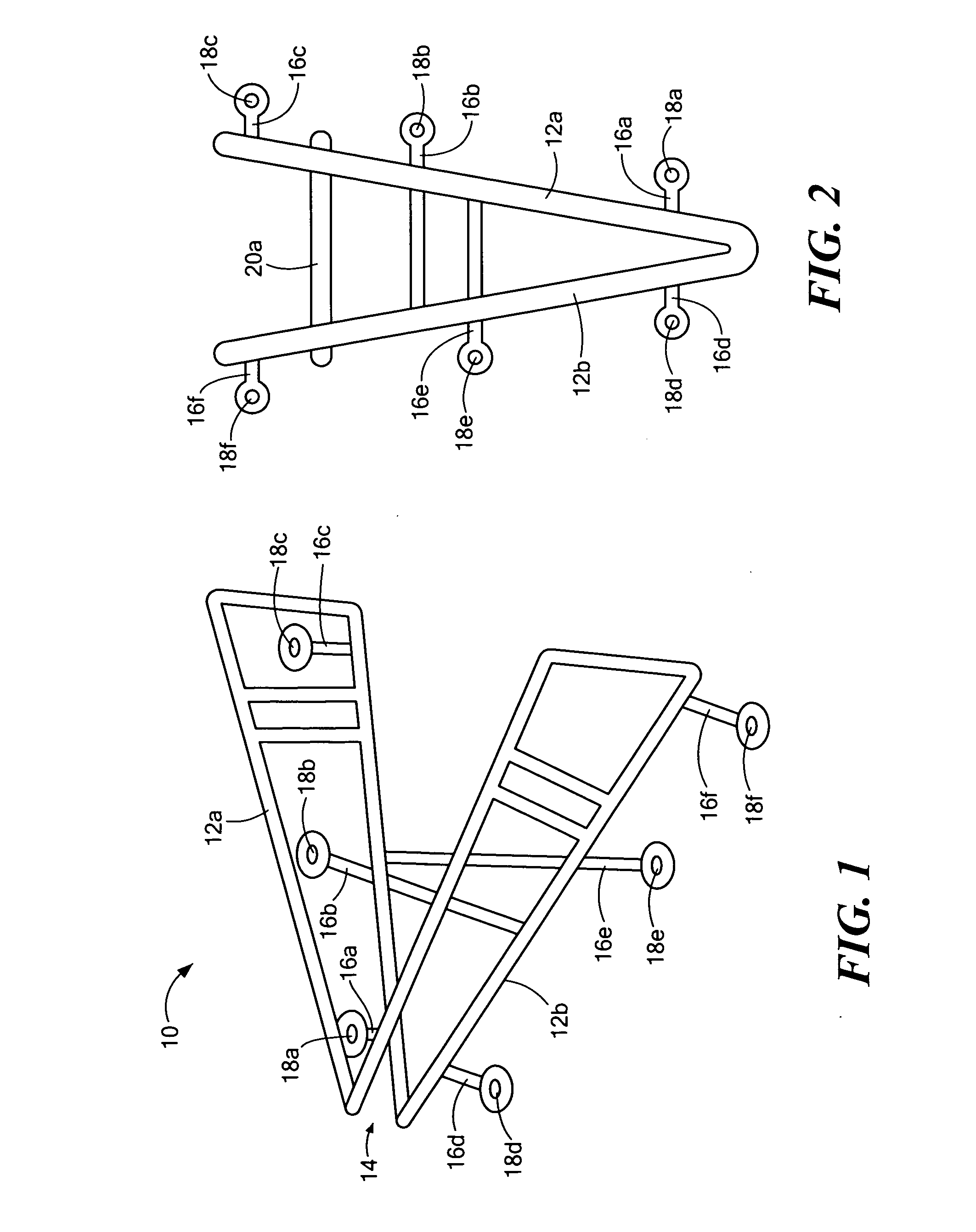
[0033]FIGS. 1-2 show an example of a tibial tuberosity advancement implant 10 in accordance with the subject invention. First and second arms 12a and 12b are pivotally joined at apex 14. Tabs 16a-16c extend outwardly from an edge of each arm 12a and tabs 16d-16f extend outwardly from arm 12b. Each tab terminates in an ancho...


PUM


Abstract

A tibial tuberosity advancement implant with first and second arms pivotally joined at an apex. Tabs including anchor apertures extend from each arm for attachment of the arms in a traverse osteotomyized tibia. A selection of various width keys are each insertable between the arms for setting the distance between the arms and the width of the osteotomyized tibia.

Description

FIELD OF THE INVENTION[0001]The subject invention relates to implants including a tibial tuberosity advancement implant.BACKGROUND OF THE INVENTION[0002]The veterinary surgical procedure known as tibial tuberosity advancement is used to correct a rupture of the CrCL in the knee of a dog. “See Tibial Tuberosity Advancement” by Dr. Jeff Mayo incorporated herein by this reference. Typically, a tibial tuberosity advancement includes a selection of cages, tension band plates, and forks. A jig is used to place the holes in the tibial tuberosity at the proper angle and spacing, a fork inserter is used to insert the forks to secure the tension band plate into the bone, a T-handle with spreaders is used to bend the plates and to hold the osteotomy open for testing of the cage size and insertion of the cage implant. Pins are used to lock the jig in place and a plate bender is used to bend the plates and the ears of the cage.[0003]The fork is inserted through the plate into drilled holes and t...

Claims


Application Information

Patent Timeline
IPC IPC(8): A61F2/38A61B17/58
CPCA61B17/68A61B17/8085A61B17/8095
Inventor SCHILLING, ERIC M.WOTTON, III, HAROLD M.
Owner MWI VETERINARY SUPPLY
Why Eureka
Try Eureka