Recessed aperture-coupled patch antenna with multiple dielectrics for wireless applications

a patch antenna and dielectric technology, applied in the field of patch antennas, can solve the problems of patch antenna assembly often protruding, coaxial cable connection requires manual disassembly,

Inactive Publication Date: 2005-03-15
APPLE INC
View PDF9 Cites 39 Cited by
  • Summary
  • Abstract
  • Description
  • Claims
  • Application Information

AI Technical Summary

Problems solved by technology

When conventional patch antennas are used in electronic devices two disadvantages result.
First, the coaxial cable connection requires manual disassembly if the antenna or the element to which the antenna is affixed or incorporated is extracted from the electronic device.
Second, the patch antenna assembly often noticeably protrudes from the housing of the electronic device and detracts from the device's cosmetic appearance.

Method used


Image

  • Recessed aperture-coupled patch antenna with multiple dielectrics for wireless applications
  • Recessed aperture-coupled patch antenna with multiple dielectrics for wireless applications
  • Recessed aperture-coupled patch antenna with multiple dielectrics for wireless applications

Examples


Embodiment Construction

A recessed aperture-coupled patch antenna assembly is disclosed. In the following detailed description, numerous specific details are set forth in order to provide a thorough understanding of the present invention. However, it will be apparent to one of ordinary skill in the art that these specific details need not be used to practice the present invention. In some circumstances, well-known structures and materials have not been shown or described in detail in order not to unnecessarily obscure the present invention.

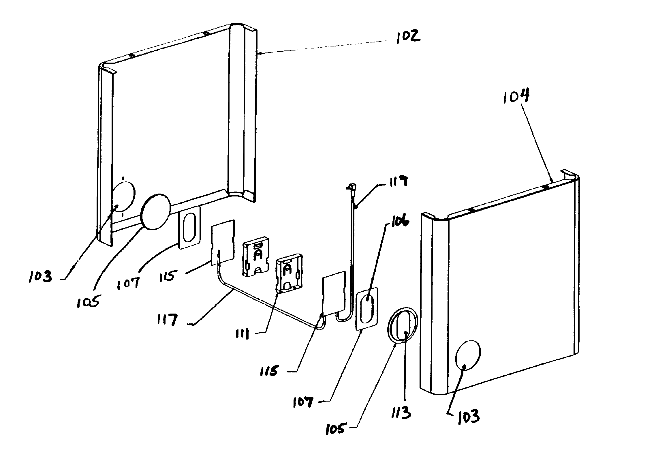
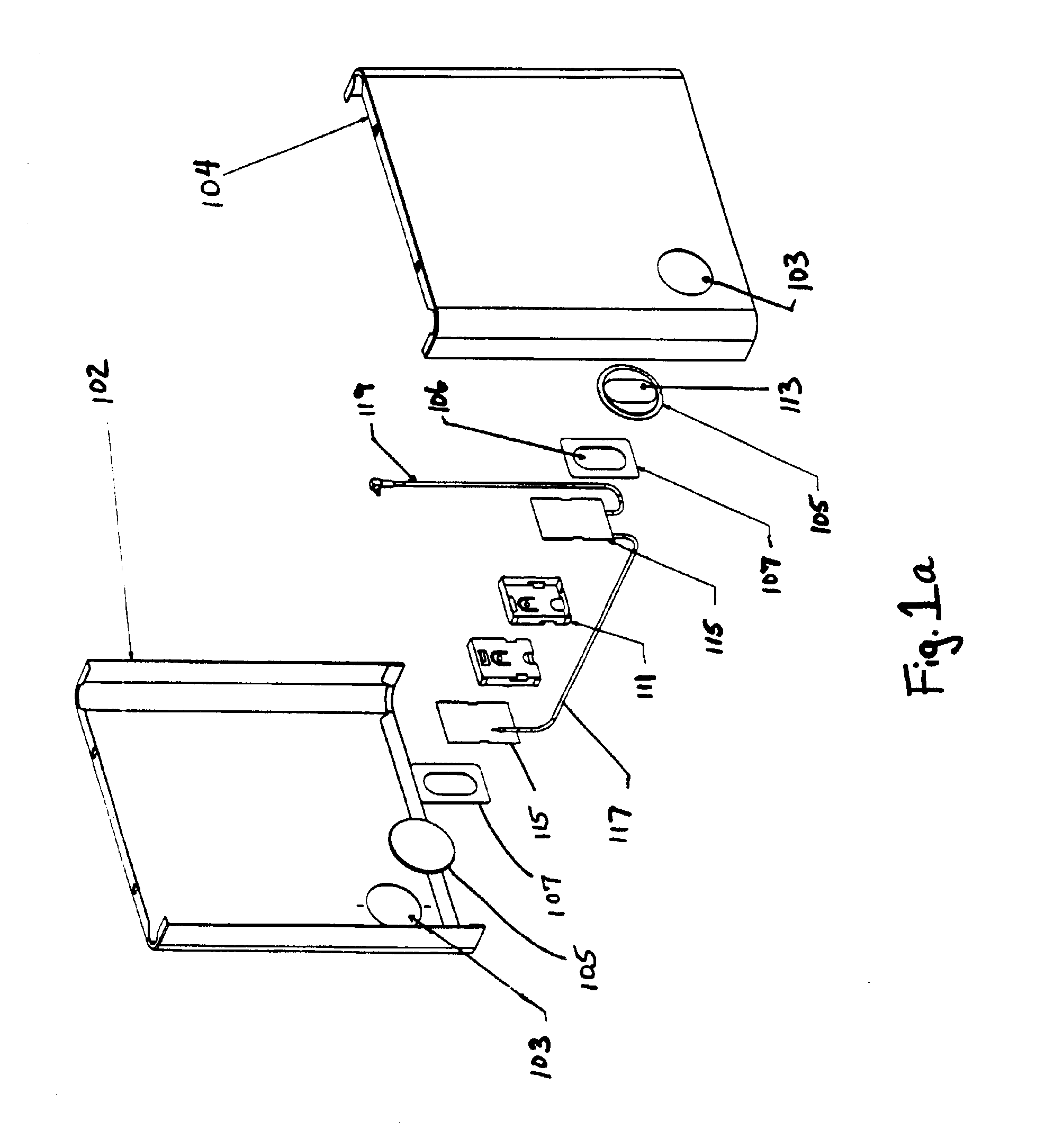
Referring now to FIG. 1a, an exploded perspective view of a patch antenna assembly is shown. Two opposing panels 102 and 104 of four-sided chassis (not shown) are illustrated. The remaining two panels have been omitted from FIG. 1a to show the various components of the patch antenna assembly. Panels 102 and 104 contain openings 103 for the ceramic antenna dielectrics 105, which support antennas 113 (metallized layers on ceramic antenna dielectrics 105). In one embodiment...


PUM


Abstract

The present invention provides an aperture-fed patch antenna assembly that is recessed into a conductive surface of an external shell of an electronic device. In one embodiment, an antenna feed attached to a removable core of the electronic device may be removed from the external shell without requiring a manual disconnecting of the antenna feed from a wireless radio modem in the electronic device. The patch antenna assembly includes a shim having an aperture therein and positioned between a primary dielectric and a printed circuit board to create a secondary dielectric between the primary dielectric and the printed circuit board. In one embodiment, the primary dielectric is ceramic and the shim is plastic.

Description

FIELD OF THE INVENTIONThe field of the invention relates to antennas, and particularly to patch antennas recessed within housings of electronic devices such as computers.BACKGROUND OF THE INVENTIONPatch antennas, also called microstrip patch antennas, are common in the art. A exemplary patch antenna may include a transmission line feed, multiple dielectrics, and a metallized patch on one of the dielectrics. Conventional patch antennas are directly coupled to their feeds by coaxial cables.When conventional patch antennas are used in electronic devices two disadvantages result. First, the coaxial cable connection requires manual disassembly if the antenna or the element to which the antenna is affixed or incorporated is extracted from the electronic device. Second, the patch antenna assembly often noticeably protrudes from the housing of the electronic device and detracts from the device's cosmetic appearance.A solution is needed that provides a patch antenna assembly that is easily e...

Claims


Application Information

Patent Timeline
Patent Type & Authority Patents(United States)
IPC IPC(8): H01Q9/04
CPCH01Q9/0407H01Q9/0457H01Q9/0442
Inventor BIRNBAUM, THOMAS J.FENWICK, STEPHEN C.ASTRIN, ARTHUR W.MARIANO, RICARDO
Owner APPLE INC
Why Eureka
Try Eureka