Hot melt adhesive system having centralized manifold and zone heating capability

Inactive Publication Date: 2005-04-26
NORDSON CORP
View PDF16 Cites 27 Cited by
  • Summary
  • Abstract
  • Description
  • Claims
  • Application Information

AI Technical Summary

Benefits of technology

[0008]The present invention provides a dispensing unit for a hot melt adhesive system in which the supply hose connections to the adhesive supply manifold are located centrally between right and left sides of the unit. The invention provides advantages in that a common length of heated hose may be used to provide liquid adhesive to one or more manufacturing lines. End users need only purchase and stock a single length of hose for use on different installations of adhesive dispensing systems. The design also improves accessibility of the heated hose cord sets to electrical connections on the controller and significantly reduces the vertical envelope or space occupied by the unit.
[0009]More specifically, the dispensing unit for a hot melt adhesive system includes a tank, a manifold, and a controller. The manifold is located adjacent the tank and is positioned between the tank and the controller. Outlet ports on the manifold are arranged to be substantially centrally located with respect to the tank-side and controller-side ends of the unit. Because the manifold is no longer located beneath the tank, the overall height of the dispensing unit may be reduced to provide a shorter service envelope. Another benefit is that a conventional pump, such as a piston pump may be located outside of the tank. This permits easier serviceability of the pump and vertical pump orientation which results i

Problems solved by technology

This asymmetry can be problematic when a single dispensing unit is positioned between two manufacturing lines to supply adhesive to the two lines.
It can also be problematic if separate dispensing units are used to supply separate manufacturing lines.
This is especially problematic when the heater is energized to melt solid or semi-solid adhesive that has been added to the tank during operation when the tank level is low.
This problem is sometimes referred to as thermal shock and is caused by the control system's attempt to rapidly melt the relatively cool, solid or sem

Method used


Image

  • Hot melt adhesive system having centralized manifold and zone heating capability
  • Hot melt adhesive system having centralized manifold and zone heating capability
  • Hot melt adhesive system having centralized manifold and zone heating capability

Examples


Example

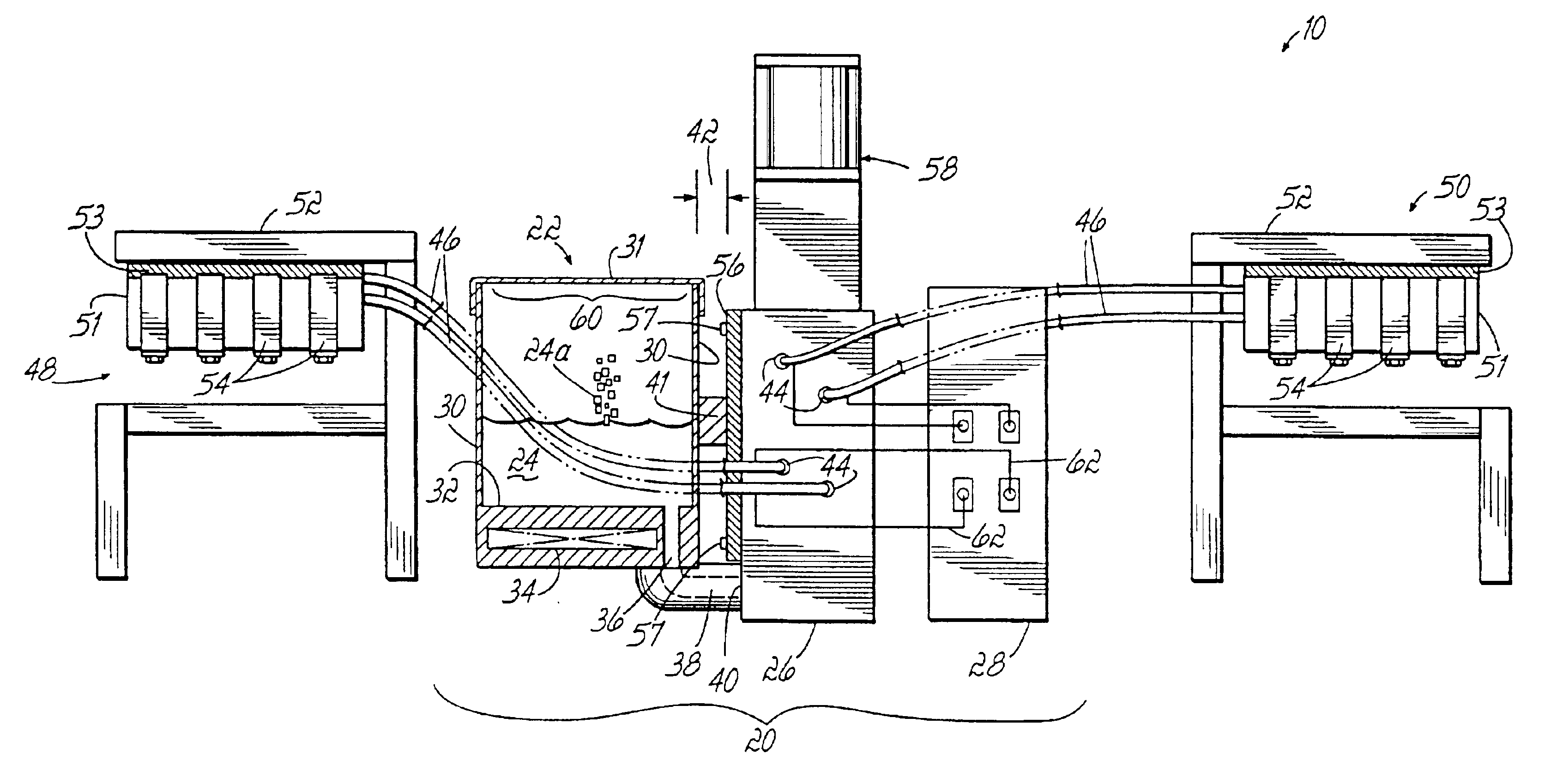
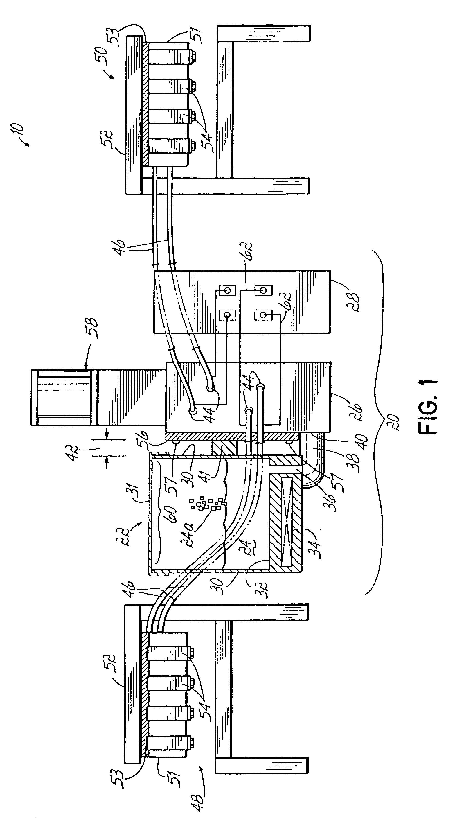
[0019]Referring to FIG. 1, a hot melt adhesive system 10 is shown, including a dispensing unit 20 which incorporates principles of the present invention. The dispensing unit 20 includes a tank 22 for receiving and melting solid or semi-solid adhesive material 24a, a manifold 26 connected to the tank 22, and a controller 28. The tank 22 comprises side walls 30, a removable cover 31, and base 32 which includes one or more tank heaters 34 for melting and heating the liquid adhesive material 24 in the tank 22. The base 32 may be integral with the tank 22 and one or more heaters 34 may be cast in place. A tank outlet 36 proximate the base 32 is coupled to a passage 38 which connects to an inlet 40 of the manifold 26.

[0020]The manifold 26 is mounted to a side wall 30 of the tank 22 with a spacer 41 and is spaced from the tank 22 a distance 42 sufficient to provide thermal isolation of the tank 22 and manifold 26. In an exemplary embodiment, the spacer 41 is made from aluminum. A verticall...


PUM


Abstract

A dispensing unit for a hot melt adhesive system has a manifold centrally located within the dispensing unit to permit commonality between heated hoses of substantially the same length used to supply adhesive guns at either side of the dispensing unit. The dispensing unit also includes a manifold that is thermally isolated from the adhesive tank. The manifold has a heater that is independent of the tank heater for more precise temperature control of adhesive flowing through the manifold. A pump coupled to the manifold is located external to the tank and is heated by the manifold heater.

Description

CROSS-REFERENCE TO RELATED APPLICATIONS[0001]This application claims the benefit of U.S. Provisional Application Nos. 60 / 345,886 and 60 / 345,887 both filed on Oct. 29, 2001, and the disclosures of which are hereby incorporated by reference herein.FIELD OF THE INVENTION[0002]The present invention pertains to dispensing systems for dispensing flowable material, and more particularly to hot melt adhesive dispensing systems.BACKGROUND OF THE INVENTION[0003]Thermoplastic adhesives, otherwise known as “hot melt” adhesives have been widely used in industry for adhering many types of products. Hot melt adhesive dispensing systems generally include one or more dispensing guns, heated hoses connected to the guns, and a dispensing unit for melting and supplying heated liquid adhesive to the guns through the heated hoses. The dispensing units of conventional hot melt adhesive systems include a tank, a heater, a pump, a manifold, and a controller. The heater is located in a base of the tank and t...

Claims


Application Information

Patent Timeline
IPC IPC(8): B05C11/10B05C5/04
CPCB05C11/1044B05C11/1042Y10T137/85938
Inventor JETER, DAVID R.ANDEL, DAVID F.
Owner NORDSON CORP
Why Eureka
Try Eureka