Motor-operated valve

a motor-operated valve and valve shaft technology, which is applied in the direction of valve details, valve arrangement, operating means/releasing devices, etc., can solve the problems of inability to keep the state of the valve being closed, the valve spindle v is lifted and cannot keep the valve closed, and the valve spindle to move up and down slightly, etc., to achieve improved stability of the valve spindle upon closing the valve, and improve the alignment

Inactive Publication Date: 2005-08-02
CHIYODA KUCHOKIKI
View PDF12 Cites 12 Cited by
  • Summary
  • Abstract
  • Description
  • Claims
  • Application Information

AI Technical Summary

Benefits of technology

[0009]An object of the present invention is to provide an improved electrically driven valve wherein the state of the valve's being closed is kept excellently when exciting pulses are applied in the direction of further closing the valve in the state of the valve's being closed as in the case of the initializing of the electrically driven valve.
[0011]Accordingly, rotation of the rotation driving member causes the valve spindle to be rotated through the interlocking part and moved forwards and backwards by means of the screw thread part. Upon closing the valve, the valve spindle is tightened to the valve seat by means of the screw thread part, so that stability of the valve spindle upon closing the valve is increased. Meanwhile, for example, upon the initializing of the electrically driven valve, when exciting pulses are supplied excessively to the stepping motor upon closing the valve and the rotation driving member shifts in a predetermined angle in the direction of opening the valve, the bring-back preventing part causes the rotation driving member's shifting to have no interlocking with the valve spindle, thereby preventing the valve spindle from moving up and down with the screw thread part being slackened and tightened, resulting in that the state of the valve's being closed is kept excellently.
[0013]Accordingly, in the state of the valve's being closed, specific magnetic poles on the stator and the rotor of the stepping motor face mutually to have a stable positional relationship in the direction of turning. Hence, in association with the sure operating mechanism that allows the valve spindle to move forwards and backwards through the screw thread part, dispersion of specific amounts of exciting pulses supplied from the state of the valve's being closed to the start of opening the valve is reduced. Thus, even when the initializing of the valve is repeated, a stable valve-opening operation is carried out, enabling the extent of hysteresis in the flow control properties to be lowered, improving controllability, whereby enabling controlling temperatures or the like for air-conditioners to be carried out excellently.

Problems solved by technology

In the above conventional art, upon closing the valve, the valve head H is pushed against the valve seat Z by the force of the valve spindle urging spring Q. Thus, when upstream and downstream sides with respect to the closed valve seat Z part are subjected, in the direction of opening the valve, to an excessively large differential pressure which results from a transitional change of refrigerant pressure or other causes and is larger than the urging force of the spindle-urging spring Q, such problem is caused that the valve spindle V is lifted and not able to keep closing the valve.
In this case, there is a fear that the stepping motor M steps out and the rotor R causes bringing back of the valve spindle, thereby causing the valve spindle to move up and down slightly.
Thus, the rotor R turns regularly or irregularly in a certain extent of angle α ({circle around (4)}), and the valve spindle moves up and down with the screwing being slackened and tightened, resulting in that the state of the valve's being closed is not able to be kept.

Method used


Image

  • Motor-operated valve
  • Motor-operated valve
  • Motor-operated valve

Examples


Embodiment Construction

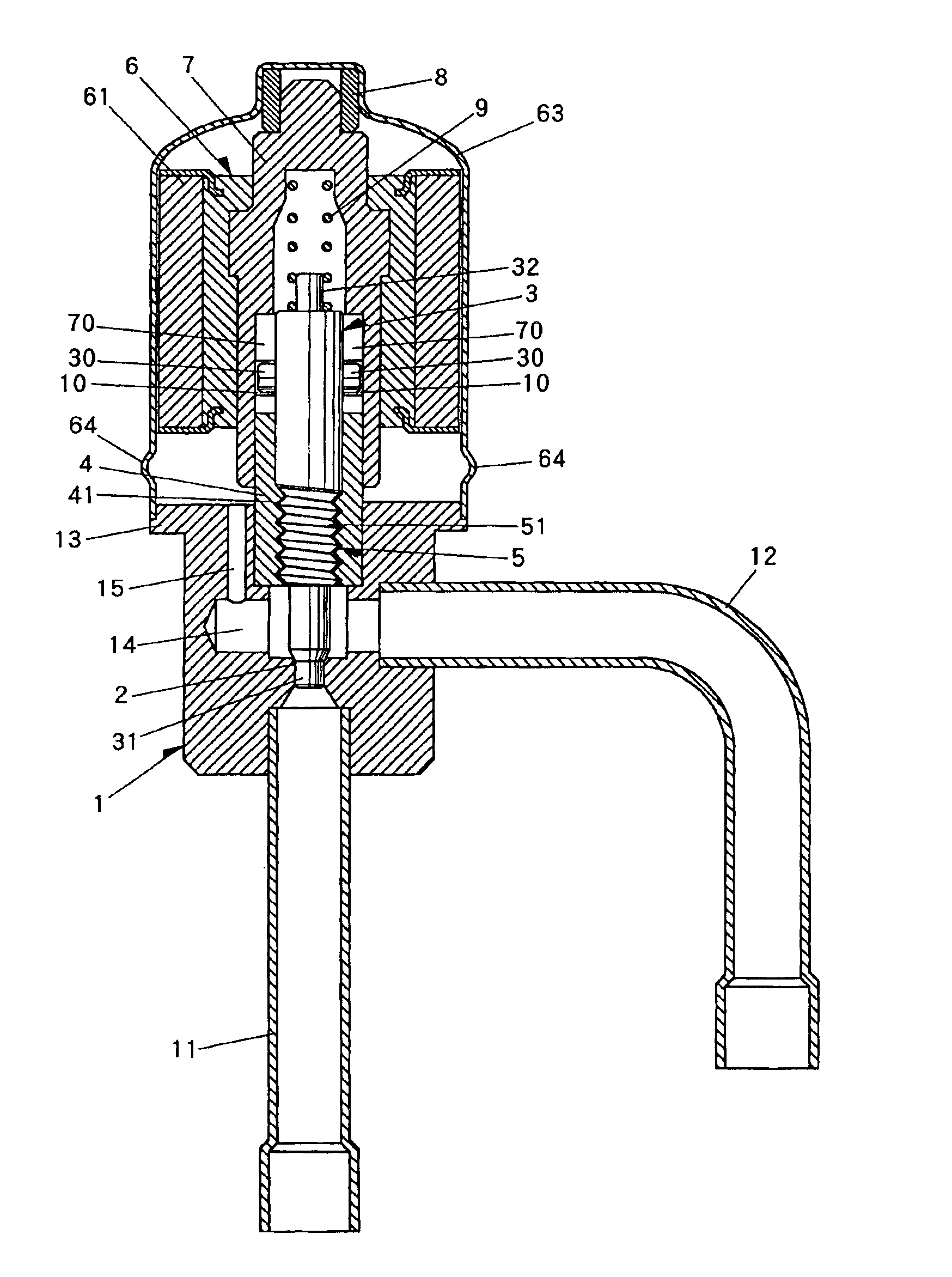
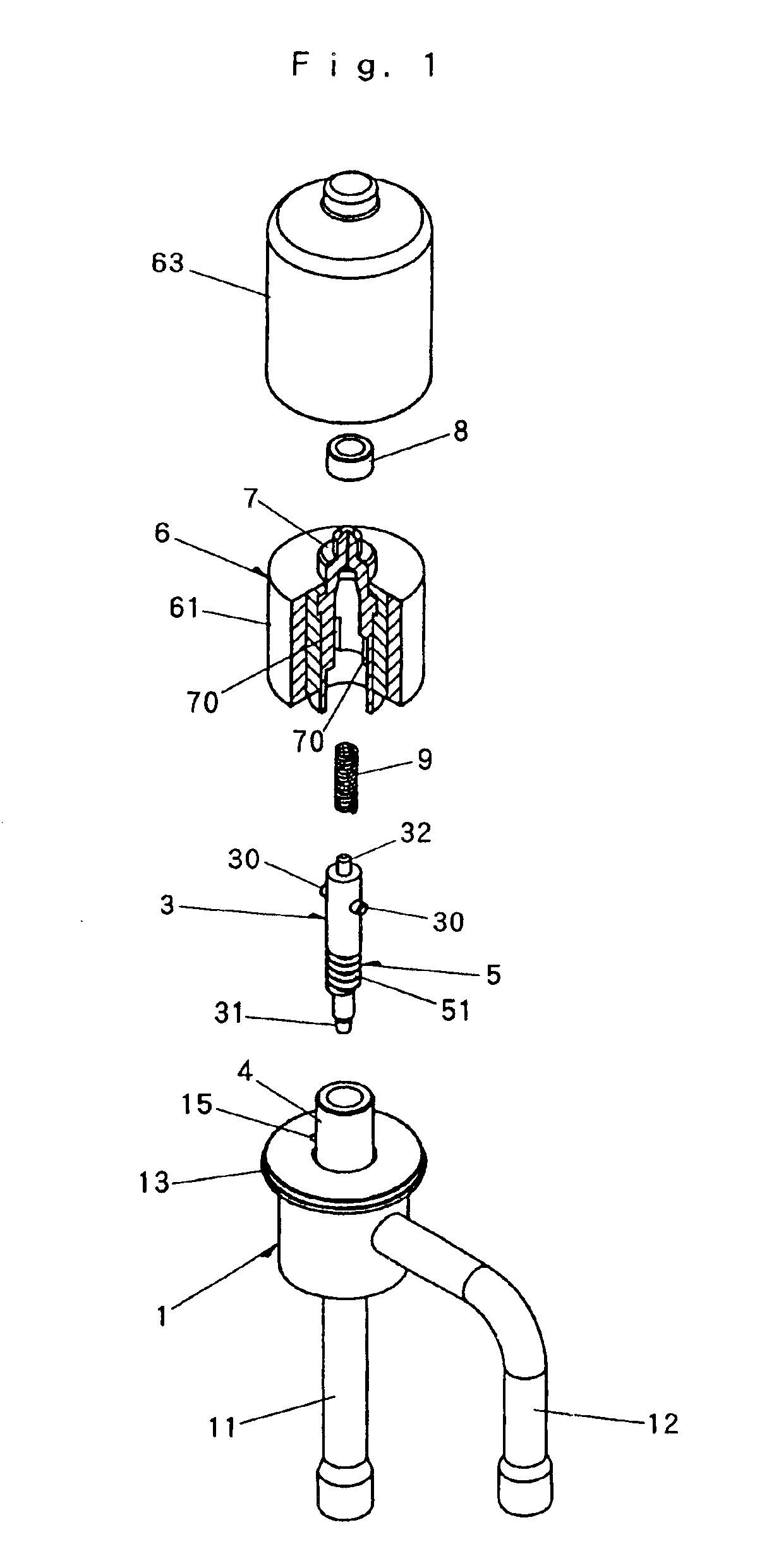
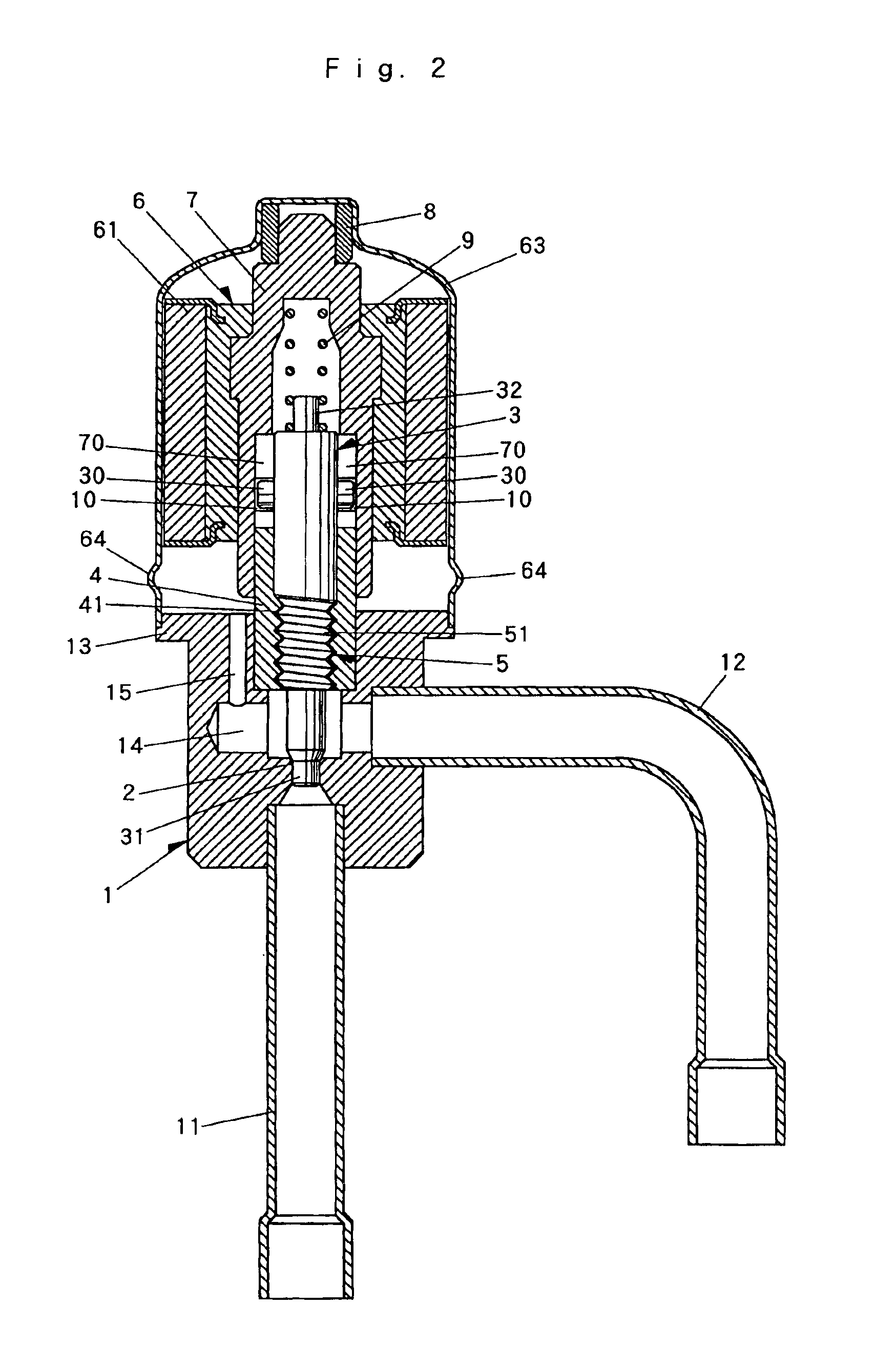
[0028]As shown in FIGS. 1 and 2, a first connecting piping 11 and a second connecting piping 12 are coupled to a valve body 1 in a manner of extending rectangularly. The first connecting piping 11 is connected, for example, to the outdoor unit side and the second connecting piping 12 to the indoor unit side. A valve seat 2 is formed inside the valve body 1 and a valve head 31 in the shape of a needle integrated at an end of a valve spindle 3 in the shape of a cylinder faces the valve seat 2.

[0029]The valve spindle 3 is provided with a screw thread part 5 which comprises a male thread 51 to be screwed with a female thread 41, which is formed on the inside of a lower bearing 4 press-fit into the valve body 1, to move the valve spindle 3 forwards and backwards. The screw thread part 5 consists of a larger lead screw thread which has larger thread lead r with respect to specific peripheral extent q corresponding to an average thread diameter, i.e., the thread gradient r / q is set to be 8...


PUM


Abstract

A valve spindle is provided with a screw thread part which meshes with a valve body to move the valve spindle forwards and backwards. Provided between a rotation driving member and the valve spindle is an interlocking part which transmits a force of rotation of the driving member to the valve spindle and allows the valve spindle's forward and backward movement following its rotation. A bring-back preventing part is provided at a location continuous with the interlocking part to prevent movement of the valve spindle in response to rotation of the driving member in the direction of opening the valve on the basis of exciting pulses excessively supplied to the stepping motor during a valve closing operation.

Description

FIELD OF THE INVENTION[0001]The present invention relates to an electrically driven valve arranged mainly on a refrigerant piping of an air conditioner and a refrigerating apparatus to control a flow or the like.BACKGROUND OF THE INVENTION[0002]The electrically driven valve of this kind comprises a valve spindle V having a valve head H that is seated on or moved away from a seat Z provided in a valve body D as exemplified in FIG. 12 and as disclosed in Japanese Patent No. 3181118. A bush P having an internal thread F and a bearing part J is fixed in the valve body D while fixed in a rotor R of a stepping motor M is a valve holder W having an external thread T to mesh with the internal thread F and a journal K to slide on the bearing part J.[0003]The valve spindle V is assembled in the valve holder W and a fixing ring L is fit onto an open side. An upper part of the valve holder W is inserted into a receiving member G fixed on a rotor casing C, and a return spring U is interposed bet...

Claims


Application Information

Patent Timeline
Patent Type & Authority Patents(United States)
IPC IPC(8): F16K31/04F16K31/10
CPCF16K31/047F16K31/105
Inventor YONEZAWA, TORU
Owner CHIYODA KUCHOKIKI
Why Eureka
Try Eureka