

Variable geometry turbine
a variable geometry turbine and turbine technology, applied in the direction of machines/engines, reaction engines, liquid fuel engines, etc., can solve the problems of engine cylinder pressure approaching or exceeding acceptable limits, the practicable limit of the inlet passage can be closed, and the operation of variable geometry turbines
- Summary
- Abstract
- Description
- Claims
- Application Information
AI Technical Summary
Benefits of technology
Problems solved by technology
Method used
Image

Examples
Embodiment Construction
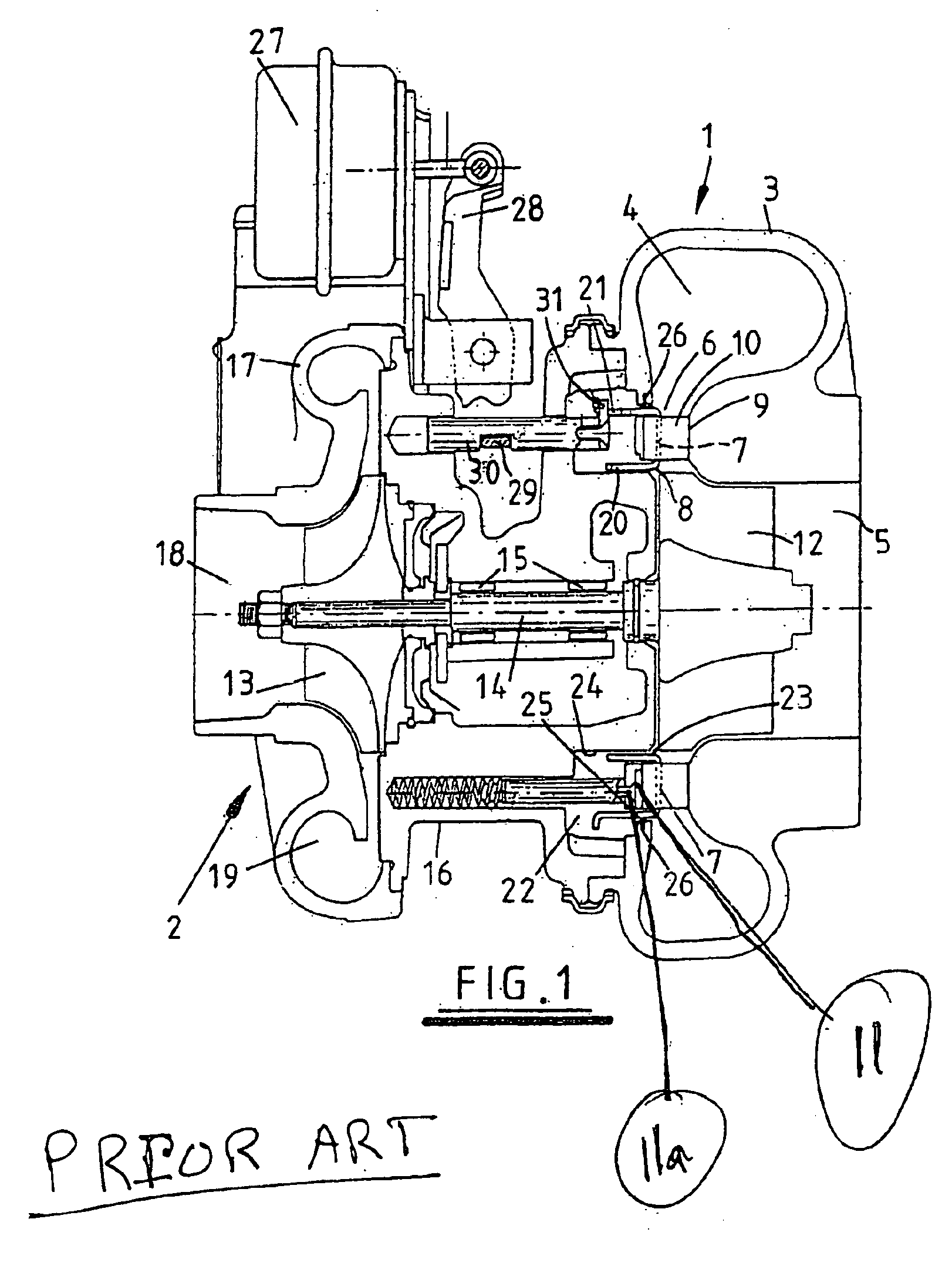
[0020]Referring to FIG. 1, this illustrates a known turbocharger as disclosed in U.S. Pat. No. 5,044,880. The turbocharger comprises a turbine stage 1 and a compressor stage 2. The turbine stage 1 is a variable geometry turbine comprising a turbine housing 3 defining a volute or inlet chamber 4 to which exhaust gas from an internal combustion engine (not shown) is delivered. The exhaust gas flows from the inlet chamber 4 to an outlet passageway 5 via an annular inlet passageway 6 defined on one side by a radial wall 7 of a moveable annular member 8, referred to herein as a nozzle ring, and on the other side by a facing radial wall 9 of the housing 3. An array of nozzle vanes 10 extend through slots in the nozzle ring 8 across the inlet passageway 6 from a vane support ring 11 which is mounted on support pins 11a. The arrangement is such that the degree to which the vanes 10 extend across the inlet passageway 6 is controllable independently of the nozzle ring 8 and will not be descri...
PUM
 Abstract
Description
Claims
Application Information