Gear-driven shears provided with a curved plate on a movable jaw

a technology of movable jaws and curved plates, which is applied in the direction of metal working apparatuses, secateurs, etc., can solve the problems of low material cost, troublesome blocking of the jaw, and lack of flexibility, so as to facilitate the user's use more practically and effectively, and the effect of less labor in operation

Inactive Publication Date: 2005-08-30
HUNG CHUAN HSIAN INDS
View PDF7 Cites 41 Cited by
  • Summary
  • Abstract
  • Description
  • Claims
  • Application Information

AI Technical Summary

Benefits of technology

[0012]2. Mainly with the added curved plate, the opening and closing of the movable jaw is more flexible and intensive, and therefore result in a supplementary interplay to facilitate the user to use them more practically and effectively with less labor in operation. It meets the new-model patent requirement of advancement.
[0013]Also, with the added curved plate, the tooth edge of the movable jaw will be installed on the curved plate and change the previously integrality of the tooth edge. Because the curved plate is suitable to be made of flexible materials, it is easier to process the tooth edge. While the movable jaw which must be made of hard steel can also omit the tooth edge so as to simplify the structure and decrease the processing difficulty. As for the industry, it can therefore reduce production costs and produce better products.

Problems solved by technology

1. One end of the movable jaw is rotating by means of gear's meshing with the gear wheel module. This structure is lack of flexibility despite the character of toughness because the movable jaw is made of hard steel as a whole. Therefore when trimming sticks, it is easier to cause a troublesome problem of being blocked off no matter when it is closing or opening.
2. One end of the corresponding grip of the movable jaw must be in the gear shape. It must be made of hard steel because the movable jaw should have a function of cropping and cutting. But the cost of material is comparatively high and it is not easy to produce so the integrative gear structure started from the end of jaw will obviously increase costs and it acts against economic benefits.

Method used


Image

  • Gear-driven shears provided with a curved plate on a movable jaw
  • Gear-driven shears provided with a curved plate on a movable jaw
  • Gear-driven shears provided with a curved plate on a movable jaw

Examples


Embodiment Construction

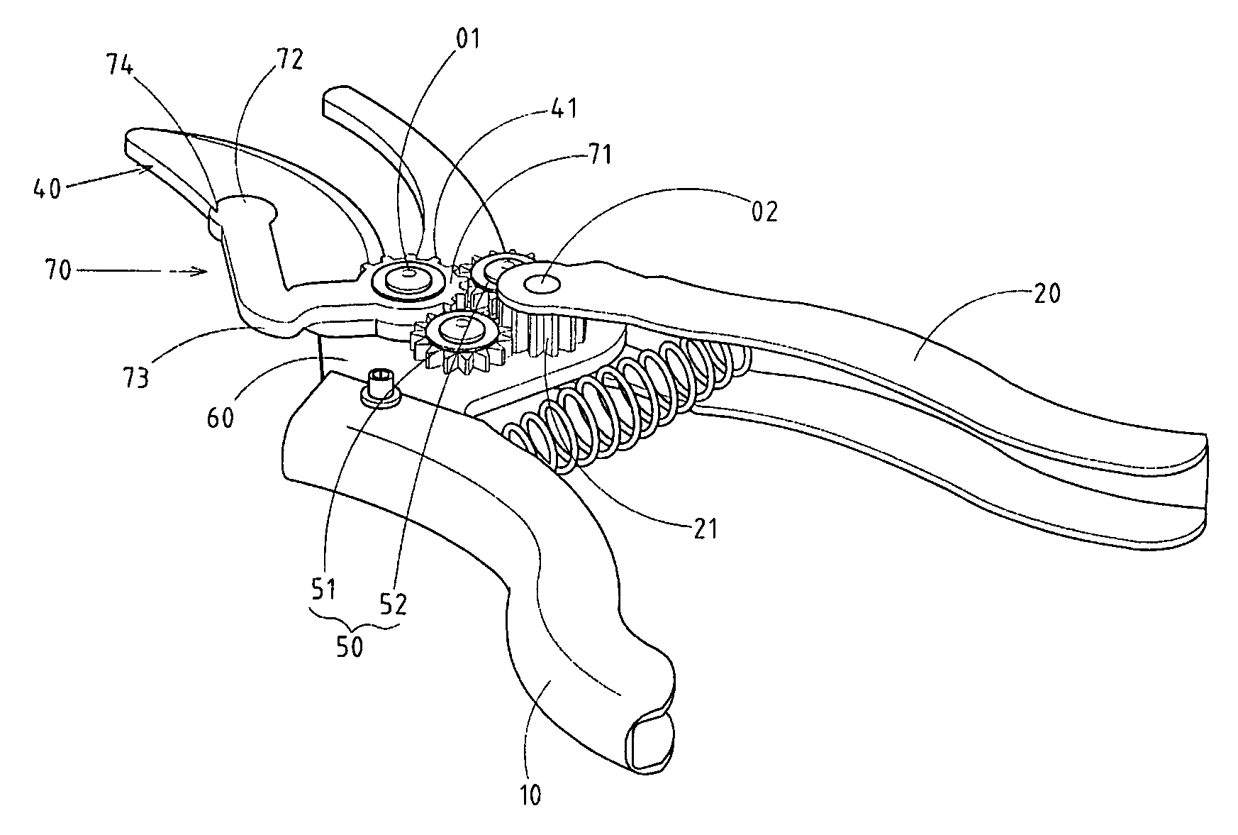
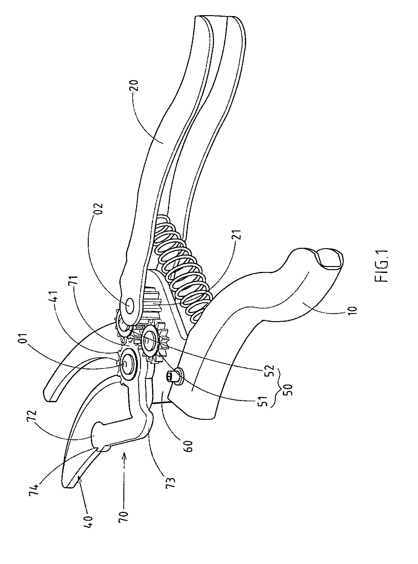
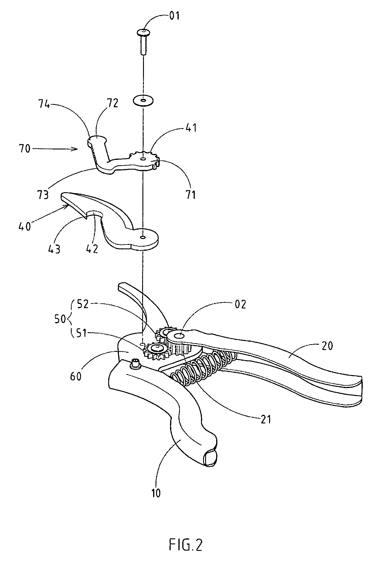
[0019]As shown in FIGS. 1–4, there is a gear-drive shear embodied in the present invention.

[0020]The present invention includes a first grip 10, second grip 20, fixed jaw, movable jaw 40 and gear wheel module 50, among which, the fixed jaw and the first grip are connected together at a joint of plate assembly module 60 in the shape of an ampliative plate. The corresponding ends of the movable jaw 40 and the second grip 20 are installed slanting on the plate assemble module 60 respectively to the corresponding first pivot axle 01 and second pivot axle 02. The corresponding ends of the movable jaw 40 and the second grip 20 are equipped with tooth edges 41, 21 respectively. The gear wheel module 50 consists of the first gear wheel 51 and the second gear wheel 52. These two groups of gears are installed between the corresponding ends of the movable jaw 40 and the second grip 20 on the plate assembly module 60, among which, the same sides of these two groups of gears 51, 52 jointly mesh ...


PUM


Abstract

Gear-driven shears include two grips, the fixed jaw, and the movable jaw and gear wheel module. The fixed jaw and the first grip are connected together at a joint of plate assembly module. The corresponding ends of movable jaw and the second grip are installed on the first pivot axle and second pivot axle of the plate assemble module. The characteristic of the invention is that one curved plate is installed additionally on one side of the movable jaw. Its first end is also installed on the first pivot axle of the plate assembly module sharing the same rotating point with the movable jaw. Meanwhile it is installed on the first edge of the curved plate together with the first tooth edge of the movable jaw. The second edge of the curved plate is equipped with wedge, which is locked in the notch on one side of the movable jaw. The middle section of curved plate is made into a curve.

Description

RELATED U.S. APPLICATIONS[0001]Not applicable.STATEMENT REGARDING FEDERALLY SPONSORED RESEARCH OR DEVELOPMENT[0002]Not applicable.REFERENCE TO MICROFICHE APPENDIX[0003]Not applicable.FIELD OF THE INVENTION[0004]The present invention relates generally to gear-driven shears, and more particularly to gear-driven shears which have a movable jaw provided with a curved plate.BACKGROUND OF THE INVENTION[0005]This invention is the improvement based on the prior shear structure, especially the gear-drive shear. The characteristic of this shear structure differs from the general shear in that the movable jaw is not connected with driving grip, but by means of gear wheel module's inter-meshing so as to have an advantage in saving labor and splaying more easily and efficiently.[0006]The defects of the prior structure in practice are as follows:[0007]1. One end of the movable jaw is rotating by means of gear's meshing with the gear wheel module. This structure is lack of flexibility despite the ...

Claims


Application Information

Patent Timeline
Patent Type & Authority Patents(United States)
IPC IPC(8): B26B13/26B26B13/00A01G3/02
CPCA01G3/02B26B13/26
Inventor HUANG, CHIN-CHI
Owner HUNG CHUAN HSIAN INDS
Why Eureka
Try Eureka