Self-calibrating, multi-camera machine vision measuring system

a machine vision and multi-camera technology, applied in the direction of mechanical measuring arrangements, instruments, using mechanical means, etc., can solve the problems of long time elapse before the technician realizes that the aligner is out of calibration

Inactive Publication Date: 2005-11-22
SNAP ON INC
View PDF19 Cites 80 Cited by
  • Summary
  • Abstract
  • Description
  • Claims
  • Application Information

AI Technical Summary

Problems solved by technology

Further, even after calibration is performed, the aligner may lose calibration over time.
However, if the cameras are jarred or dismounted, or if the boom itself is bent, the aligner will lose calibration.
A long time may elapse before the technician realizes that the aligner is out of calibration.
In addition, the boom is large, expensive and presents an obstacle to vehicles entering and leaving the alignment rack.
This can be time-consuming, costly, and clumsy.

Method used


Image

  • Self-calibrating, multi-camera machine vision measuring system
  • Self-calibrating, multi-camera machine vision measuring system
  • Self-calibrating, multi-camera machine vision measuring system

Examples


Embodiment Construction

[0032]A method and apparatus for automatic calibration of a machine vision measuring system that has more than one camera is described. In the following description, for the purposes of explanation, numerous specific details are set forth in order to provide a thorough understanding of the present invention. It will be apparent, however, to one skilled in the art that the present invention may be practiced without these specific details. In other instances, well-known structures and devices are shown in block diagram form in order to avoid unnecessarily obscuring the present invention.

[0033]Structural Overview

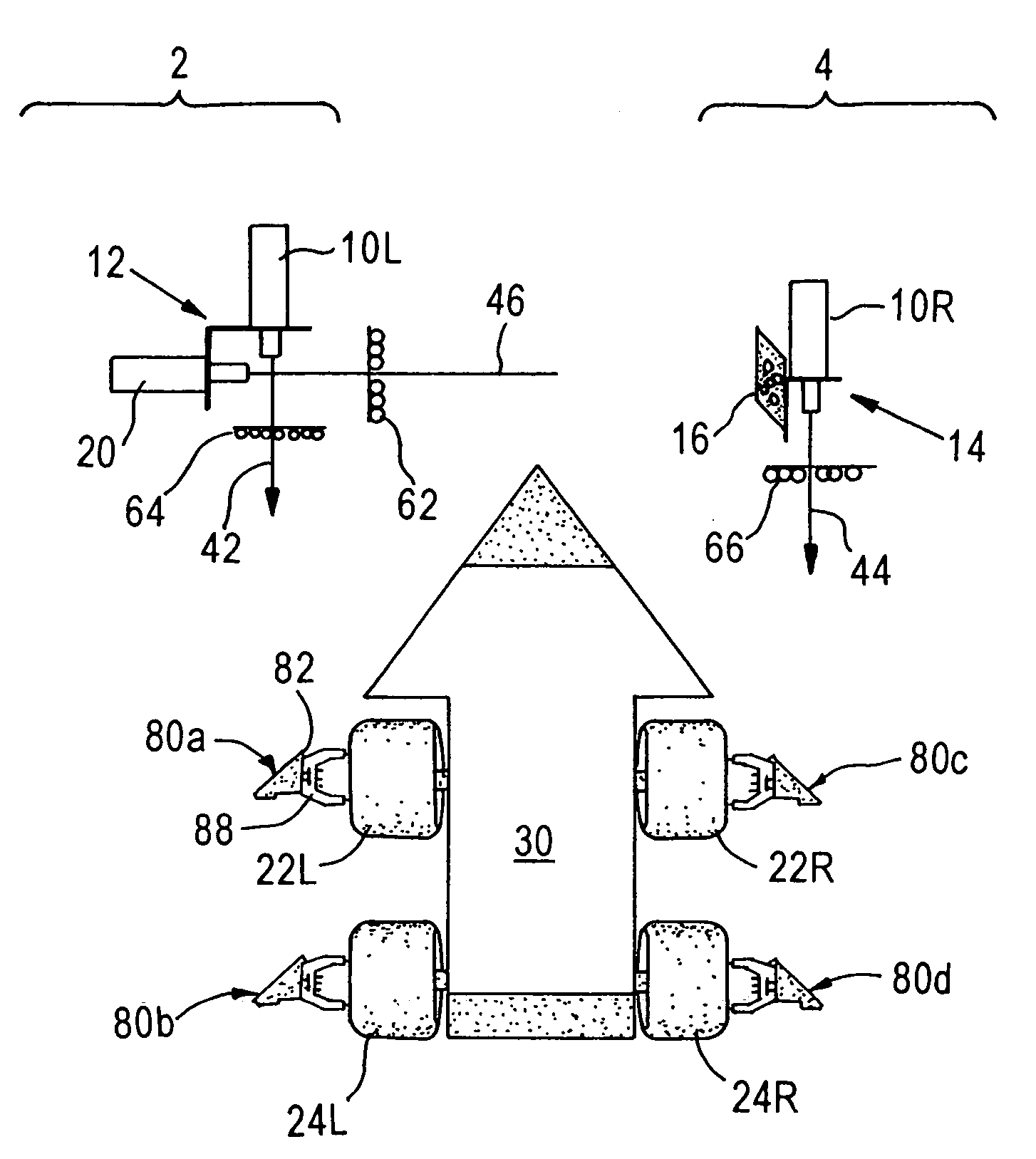
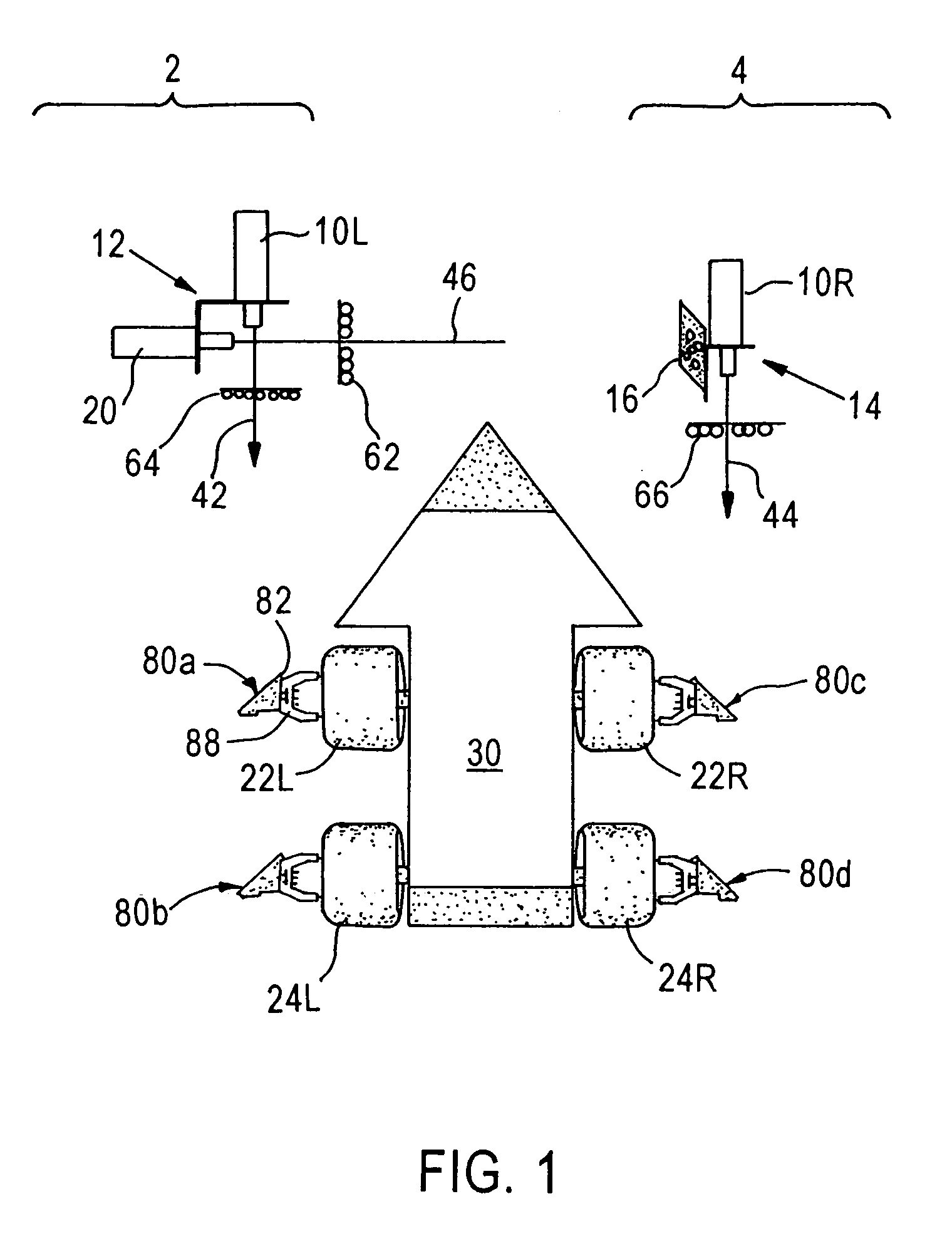
[0034]FIG. 1 is a schematic top plan view of certain elements of a computer-aided, 3D motor vehicle wheel alignment system (“aligner”) generally comprising a left camera module 2 and a right camera module 4 that are used to align wheels of a motor vehicle. Such an aligner is an example of a machine vision measuring system that has more than one camera, however, the present inve...


PUM


Abstract

An apparatus and method for calibrating machine vision measuring systems that have more than one camera are disclosed. A first calibration target is mounted in a fixed relationship to a first camera of the machine vision measuring system. A third camera mounted in a fixed relationship to a second camera of the machine vision measuring system. Second and third calibration targets are mounted in a fixed relationship to one another and viewable by the first camera and by the third camera. A data processor is programmed to compute calibration of the first camera and the second camera, based on a position of the second calibration target relative to the third calibration target and a position of the first camera with respect to the third camera. The apparatus and method provide a way to continuously measure the positions of the cameras used in the measuring system to calibrate the system.

Description

FIELD OF THE INVENTION[0001]The present invention generally relates to calibrating machine vision measuring systems that have more than one camera, and relates more specifically to apparatus and methods that provide automatic self-calibration of computer-aided, three-dimensional aligners for motor vehicle wheels.BACKGROUND OF THE INVENTION[0002]Machine vision measuring systems that have more than one camera are used in many applications. For example, wheels of motor vehicles may be aligned on an alignment rack using a computer-aided, three-dimensional (3D) machine vision alignment apparatus and a related alignment method. Examples of methods and apparatus useful in 3D alignment of motor vehicles are described in U.S. Pat. No. 5,724,743, Method and apparatus for determining the alignment of motor vehicle wheels, and U.S. Pat. No. 5,535,522, Method and apparatus for determining the alignment of motor vehicle wheels. The apparatus described in these references is sometimes called a “3D...

Claims


Application Information

Patent Timeline
Patent Type & Authority Patents(United States)
IPC IPC(8): G01B11/275G01C11/06G01C11/00G01C25/00G01S5/16G01S5/00
CPCG01B11/2755G01C11/06G01C25/00G01S5/163G01B2210/12G01B2210/143G01B2210/30G01B2210/303
Inventor JACKSON, DAVID A.ROBB, MICHAEL J.WALCHUK, DONALD L.
Owner SNAP ON INC
Why Eureka
Try Eureka