Supporting structure for planar heat pipe

a technology of supporting structure and heat pipe, which is applied in the direction of reinforcing means, basic electric elements, semiconductor devices, etc., can solve the problems of serious deformation of the heat dissipation effect, achieve improved joint strength, improve the effect of supporting structure and enhanced integration between the support member and the housing

Inactive Publication Date: 2006-04-11
PYROSWIFT HOLDING CO LIMITED
View PDF15 Cites 11 Cited by
  • Summary
  • Abstract
  • Description
  • Claims
  • Application Information

AI Technical Summary

Benefits of technology

[0005]The present invention provides an improved supporting structure for a planar heat pipe. The improved supporting structure improves the joint strength between the upper and lower lids of the heat pipe. The planarity of the housing is maintained by the improved supporting structure during vacuum process. Further, the thermal expansion caused by vapor pressure during phase transition of the heat pipe is prevented, such that the heat pipe can withstand strain and stress.
[0006]The improved supporting structure provided by the present invention comprises a housing and a support member within the housing. The housing is a hollow enclosure that includes an upper lid and a lower lid. The upper and lower lids are engaged with each to form a close hollow chamber, and a working fluid is introduced into the hollow chamber. The support member includes a planar member perforated with a plurality of holes. The support member is sintered with the upper and lower lids by power metallurgy, such that the integration between the support member and the housing is enhanced, and the joint strength between the support member and the upper and lower lids is improved.

Problems solved by technology

Therefore, a thermal resistance is resulted, and the heat dissipation effect is seriously degraded.

Method used


Image

  • Supporting structure for planar heat pipe
  • Supporting structure for planar heat pipe
  • Supporting structure for planar heat pipe

Examples


Embodiment Construction

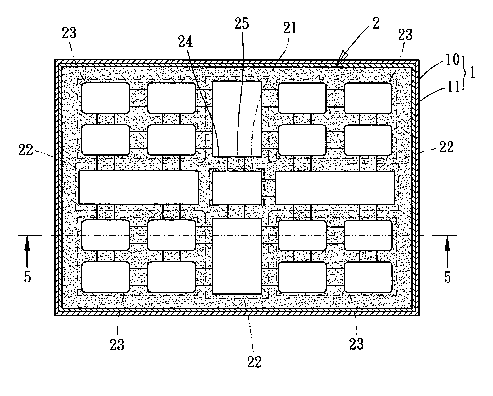
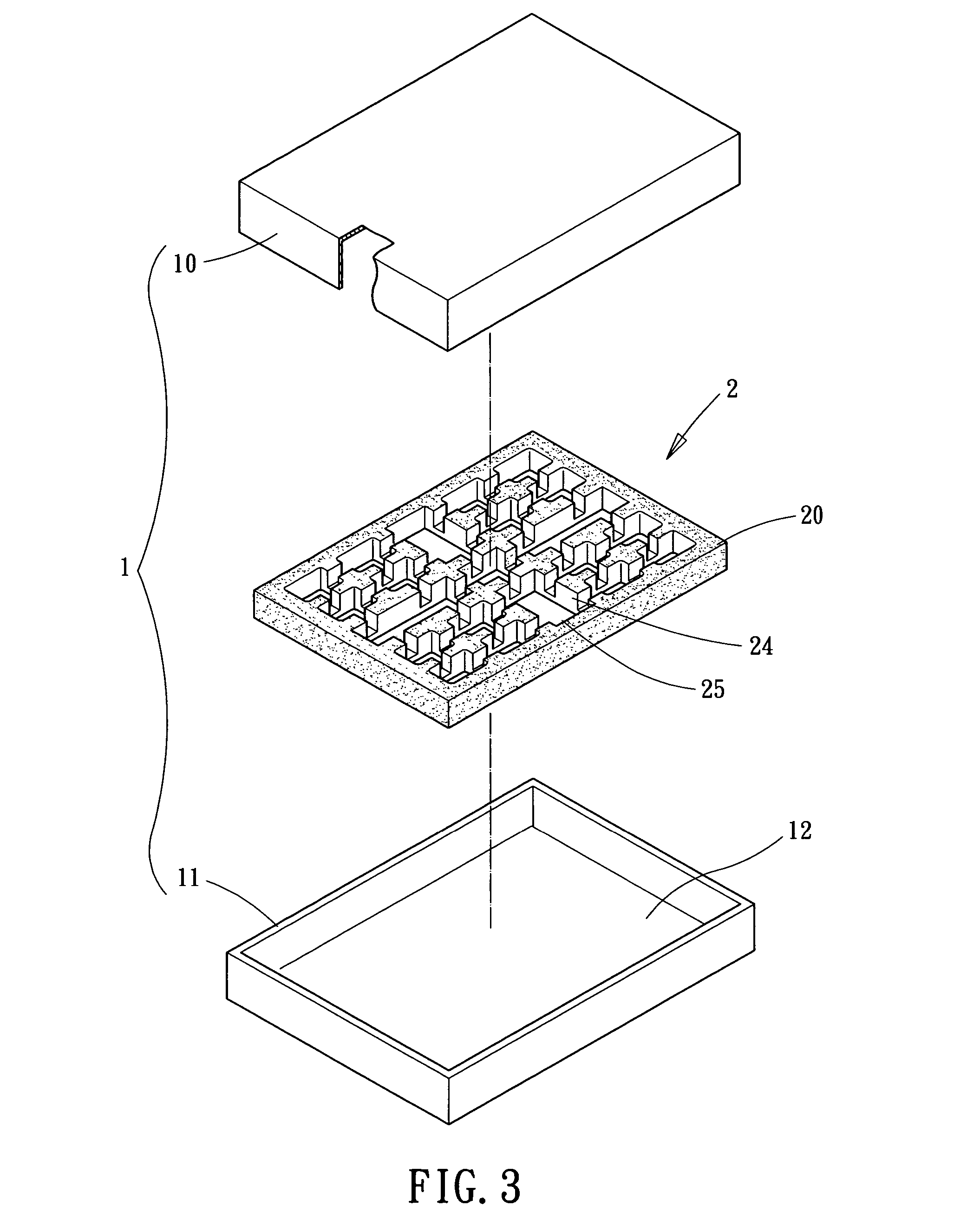
[0014]FIG. 3 shows an exploded view of a heat pipe provided by the present invention, and FIGS. 4 and 5 depict the top view and cross sectional view of the heat pipe, respectively. As shown, a planar heat pipe is provided, and the planar heat pipe includes a housing 1 and a support member 2 within the housing 2.

[0015]The housing 1 is preferably a hollow enclosure with an upper lid 11 and a lower lid 12. The upper and lower lids 11 and 12 are preferably fabricated from good conductive materials such as copper. The upper and lower lids 11 and 12 are engaged with each other to form a close hollow chamber 12, in which an adequate amount of work fluid can be injected.

[0016]The support member 2 includes a planar member perforated with a plurality of holes. The support member 2 is preferably sintered with the upper and lower lids 11 and 12 by power metallurgy, such that the support member 2 and the upper and lower lids 11 and 12 are integrated. To improve joint strength between the support...


PUM


Abstract

An improved supporting structure for a planar heat pipe, having a housing and a supporting member installed in the shell is disclosed. The housing has an upper lid and a lower lid engaged with each other to form a hollow chamber therein. The hollow chamber is filled with a working fluid. The supporting member is a planar member perforated with a plurality of holes. The supporting member is sintered with the upper and lower lids in the hollow chamber. Therefore, the housing and the supporting member are integrated together.

Description

BACKGROUND OF THE INVENTION[0001]The present invention relates to an improved supporting structure of a planar heat pipe. The supporting structure provides improved integration strength and temperature uniformity of the heat pipe, such that the more heat can be transferred thereby.[0002]The advancement of computer industry has developed a lot of high-precision electronic devices. Accompanying with the improved functions and operation speeds, these electronic devices generate more and more heat. To allow the electronic devices working under normal operational temperatures, how to efficiently dissipate the heat generated by these electronic devices has become an important topic for the research people in such industry.[0003]FIG. 1 shows a conventional planar heat pipe 1a. The planar heat pipe 1a is mainly mounted on a central processing unit (CPU) 3a. The planar heat pipe 1a includes an upper lid 11a and a lower lid 12a to construct a housing 10a and a hollow chamber 13a enclosed by t...

Claims


Application Information

Patent Timeline
Patent Type & Authority Patents(United States)
IPC IPC(8): F28D15/04H01L23/427
CPCF28D15/046H01L23/427F28F2255/18F28F2225/02H01L2924/0002H01L2924/00
Inventor WANG, CHIN WENWANG, PEI CHOAWANG, CHING CHUNG
Owner PYROSWIFT HOLDING CO LIMITED
Why Eureka
Try Eureka