Pen type optical mouse device and method of controlling the same

a mouse and pen-type technology, applied in the field of pen-type optical mouse devices, can solve the problems of degrading the accuracy of measuring the coordinates, the cursor cannot be smoothly moved on the screen of the display device, and the use place is not convenient, so as to achieve the effect of easy grasping with a hand

Inactive Publication Date: 2006-08-29
FINGER SYST
View PDF5 Cites 194 Cited by
  • Summary
  • Abstract
  • Description
  • Claims
  • Application Information

AI Technical Summary

Benefits of technology

[0020]The present invention is conceived to solve the problems as mentioned above. A primary object of the present invention is to provide a pen-type optical mouse device wherein an

Problems solved by technology

However, in such a conventional ball-type mouse, since the ball is not smoothly rotated on a slick surface, there is a limitation on a usage place and thus a mouse pad is required in order to ensure the smooth rotation of the ball.
Thus, there is a problem in that the cursor cannot be smoothly moved on the screen of the display device.
However, in such a case, there are problems in that it is troublesome to perform such an operation of moving the mouse and thus the rapidity and accuracy of measurement of the coordinates are degraded.
Particularly, there is a disadvantage in that since the shape of the mouse is different from those of general writing instruments, natural writing and drawing cannot be performed with the mouse.
Thus, there are disadvantages in that the durability of the mouse may be deteriorated and the interior of the mouse should be periodically cleaned.
In such a case, there is a problem in that since the optical mouse inevitably requires an exclusive pad, use of the mouse is limited.
However, since the shape of the mouse is different from those of general writing instruments, the movement of the mouse is performed in a state where the entire mouse is held in a user's hand and so it is difficult to achieve accurate coordinate movement.
As a result, there is a problem in that it is not easy to perform a graphic operation or to write the user's signature using the mouse.
However, the optical pointing device of the '015 patent has the following three disadvantages in performing a delicate graphic operation or smoothly writing one's signature.
First, there is a disadvantage in that it is difficult to hold the pointing device in one's hand due to large diameter thereof.
Therefore, since the installat

Method used


Image

  • Pen type optical mouse device and method of controlling the same
  • Pen type optical mouse device and method of controlling the same
  • Pen type optical mouse device and method of controlling the same

Examples


Embodiment Construction

[0054]Hereinafter, preferred embodiments of the present invention will be described in detail with reference to the accompanying drawings.

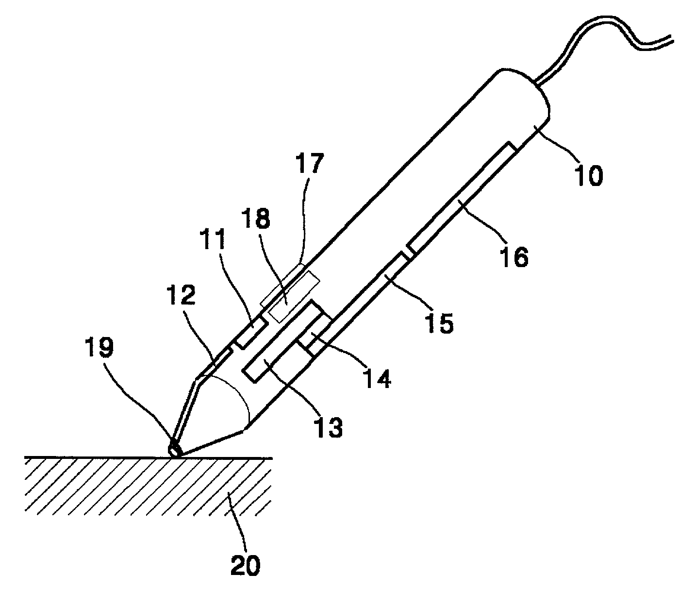
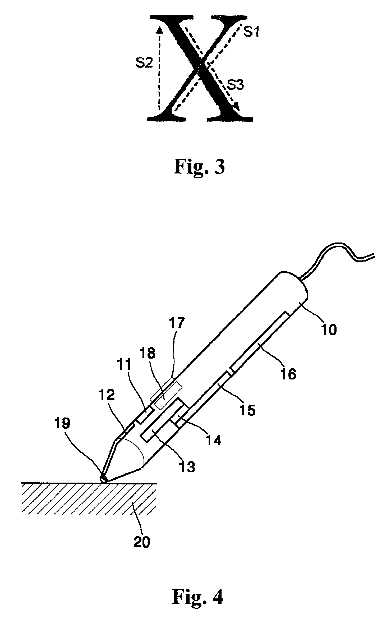
[0055]FIG. 4 is a perspective view of a pen-type optical mouse device according to the present invention.

[0056]The pen-type optical mouse device shown in FIG. 4 includes a main body 10 of the mouse device, an illumination unit 11, an imaging system 13, an image sensor 14, a control means 15, a transmitting means 16, a set button 17, a wheel switch 18, and a contact sensing means 19.

[0057]The main body 10 of the mouse device takes the form of a pen with a circular or elliptical cross-section such that a user can conveniently grasp it. Preferably, the main body 10 includes a plurality of grip portions (not shown) by which a user can hold it between his / her fingers.

[0058]The contact sensing means 19 detects contact pressure generated when a leading end of the main body 10 comes into contact with an arbitrary work surface 20 such as a desk surface, in...


PUM


Abstract

A pen-type optical mouse device indicates a cursor position or inputs writing or a movement of the pen-type optical mouse. An aspect of the pen-type optical mouse is to calculate coordinate values of the mouse device in accordance with a movement of the pen-type optical mouse device. The pen-type optical device includes an image sensor on a side of the interior of a main body of pen-type the mouse device, thereby allowing the pen-type optical mouse device to be slim and easy to hold.

Description

BACKGROUND OF THE INVENTION[0001]1. Field of the Invention[0002]The present invention relates to a pen-type optical mouse device and a method of controlling the same, and more particularly, to a pen-type optical mouse device and a method of controlling the same wherein a light guide causes light emitted from an illuminator to be incident on a surface at a predetermined angle, and a path of the light reflected from the surface is changed so that an image of the surface is imaged upon an image sensor, thereby allowing to write letters or draw a figure through a natural writing action.[0003]2. Description of the Prior Art[0004]A conventional mouse is a computer peripheral device which points a position by using a cursor displayed on a display device of a computer system and comprises a ball for allowing the change of a position and function buttons.[0005]However, in such a conventional ball-type mouse, since the ball is not smoothly rotated on a slick surface, there is a limitation on ...

Claims


Application Information

Patent Timeline
IPC IPC(8): G09G5/08G06F3/041G06F3/033G06F3/038G06F3/042
CPCG06F3/0421G06F3/03545
Inventor YANG, HONG-YOUNGLEE, SEUNG-GOL
Owner FINGER SYST
Why Eureka
Try Eureka