Compressor unit and refrigerator using the unit

a compressor unit and compressor technology, applied in the direction of machines/engines, positive displacement liquid engines, light and heating apparatus, etc., can solve the problems of increasing starting torque, and achieve the effect of increasing the starting torque and facilitating the start of the compressor

a compressor unit and compressor technology, applied in the direction of machines/engines, positive displacement liquid engines, light and heating apparatus, etc., can solve the problems of increasing starting torque, and achieve the effect of increasing the starting torque and facilitating the start of the compressor

US7134295B2Inactive Publication Date: 2006-11-14DAIKIN IND LTD

Image

  • Compressor unit and refrigerator using the unit
  • Compressor unit and refrigerator using the unit
  • Compressor unit and refrigerator using the unit

Examples


Embodiment Construction

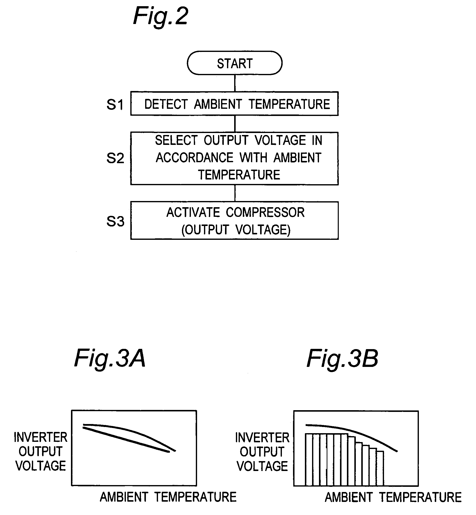
[0023]Hereinbelow, a compressor unit of the invention and a refrigerator using the unit will be described in detail with reference to embodiments shown in the accompanying drawings.

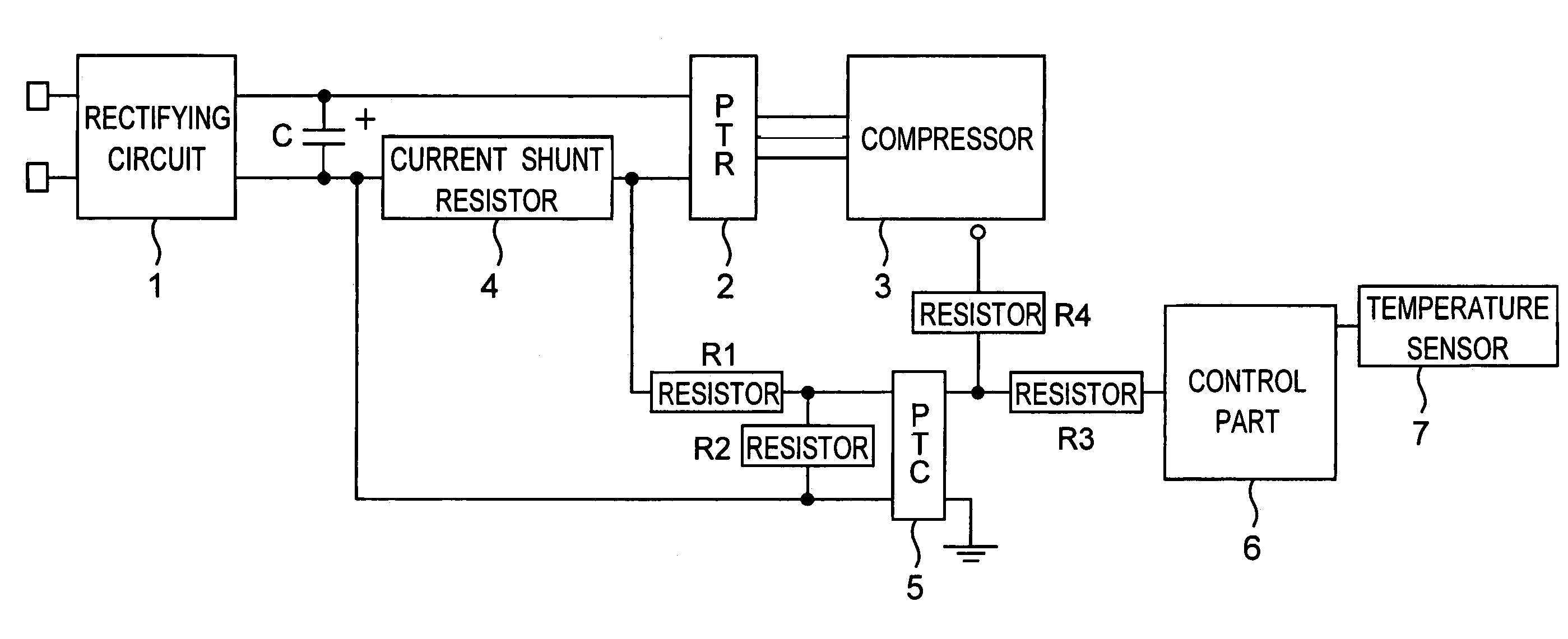
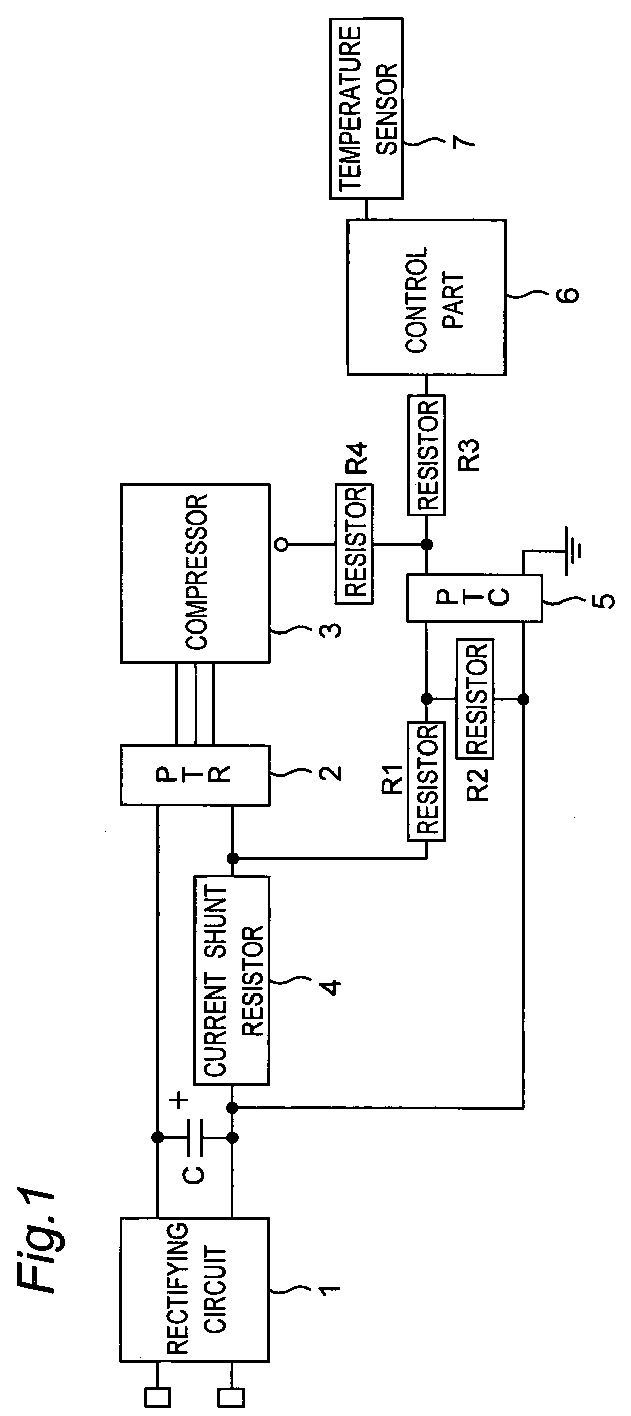
[0024]FIG. 1 is a schematic configuration of a compressor unit for use in an air conditioner in accordance with an embodiment of the invention. The compressor unit has a rectifying circuit 1 to which an AC power supply (not shown) is connected, an inverter 2 for converting a DC voltage from the rectifying circuit 1 into an AC voltage, and a compressor 3 that is driven by an output voltage from the inverter 2. An output terminal on a positive electrode side of the rectifying circuit 1 is connected to one input terminal of the inverter 2, and an output terminal on a negative electrode side of the rectifying circuit 1 is connected through a current shunt resistor 4 to the other input terminal of the inverter 2. Between both the output terminals of the rectifying circuit 1 is connected a smoothing capacitor C...


PUM


Abstract

A compressor unit includes a compressor, an inverter for driving the compressor, and an over-current protective device for protecting the inverter against an output over-current. A control part controls the output voltage of the inverter when the compressor is started based on a ambient temperature detected by a temperature sensor so that the input current of the inverter does not exceed the working current value of the over-current protective device having temperature characteristics varying according to the ambient temperature. Thereby, a start torque can be increased by increasing the output voltage of the inverter without operating the over-current protective device when the compressor is stated at a low temperature when a start load is increased.

Description

TECHNICAL FIELD[0001]The present invention relates to a compressor unit and a refrigerator using the unit.BACKGROUND ART[0002]Conventionally, there has been a compressor unit that has been used in a refrigerator having refrigerant circuits. The compressor unit has a compressor, an inverter for driving the compressor, and an over-current protective device for protecting the inverter against an output over-current. When the compressor is started, an inverter output voltage is set according to a working current value of the over-current protective device. That is, the inverter output voltage is set so that an inverter output current does not exceed the working current value of the over-current protective device and so that a maximum starting torque is gained. The over-current protective device, however, has characteristics in which a high ambient temperature decreases the working current value and in which a low ambient temperature increases the working current value, as shown in FIG. ...

Claims


Application Information

Patent Timeline
14 Nov 2006
Publication
US7134295B2
IPC
F25B1/00; F04B49/00; F25B49/00; F04B49/06
CPC
F04B49/065; F04B2203/0201; F04B2203/0202; F04B2205/10; F04B49/00; F04B49/10
Inventors
MAEKAWA, YASUNORI