Starting device for internal combustion engine
a technology for starting devices and internal combustion engines, which is applied in the direction of engine starters, electric control, ignition automatic control, etc., can solve the problems of increasing the cost of manufacture of starting devices and complicated structure of starting devices, and achieve the effect of increasing starting torqu
- Summary
- Abstract
- Description
- Claims
- Application Information
AI Technical Summary
Benefits of technology
Problems solved by technology
Method used
Image
Examples
embodiment 1
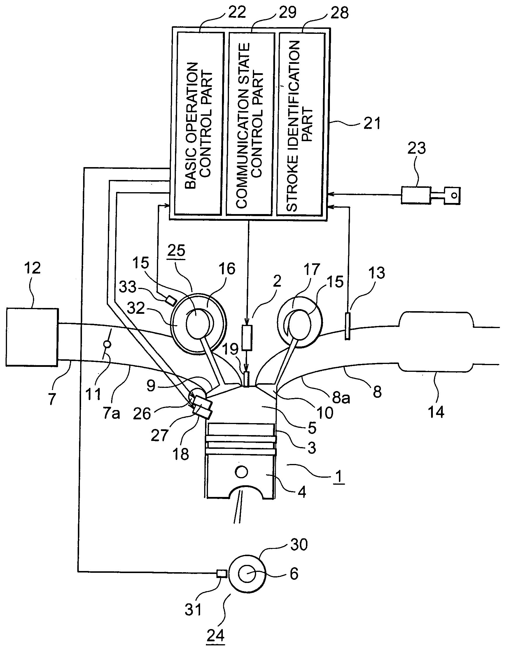
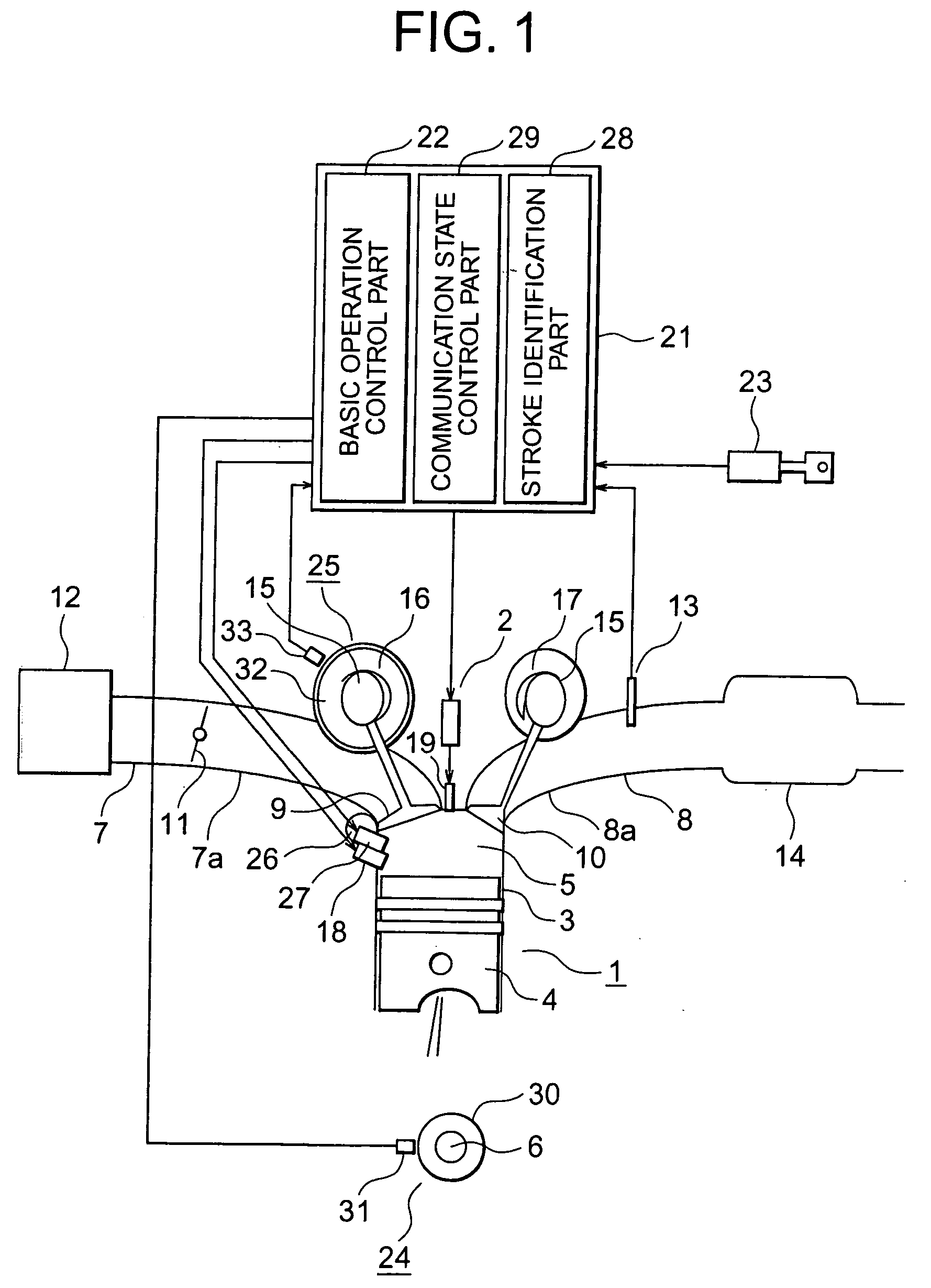
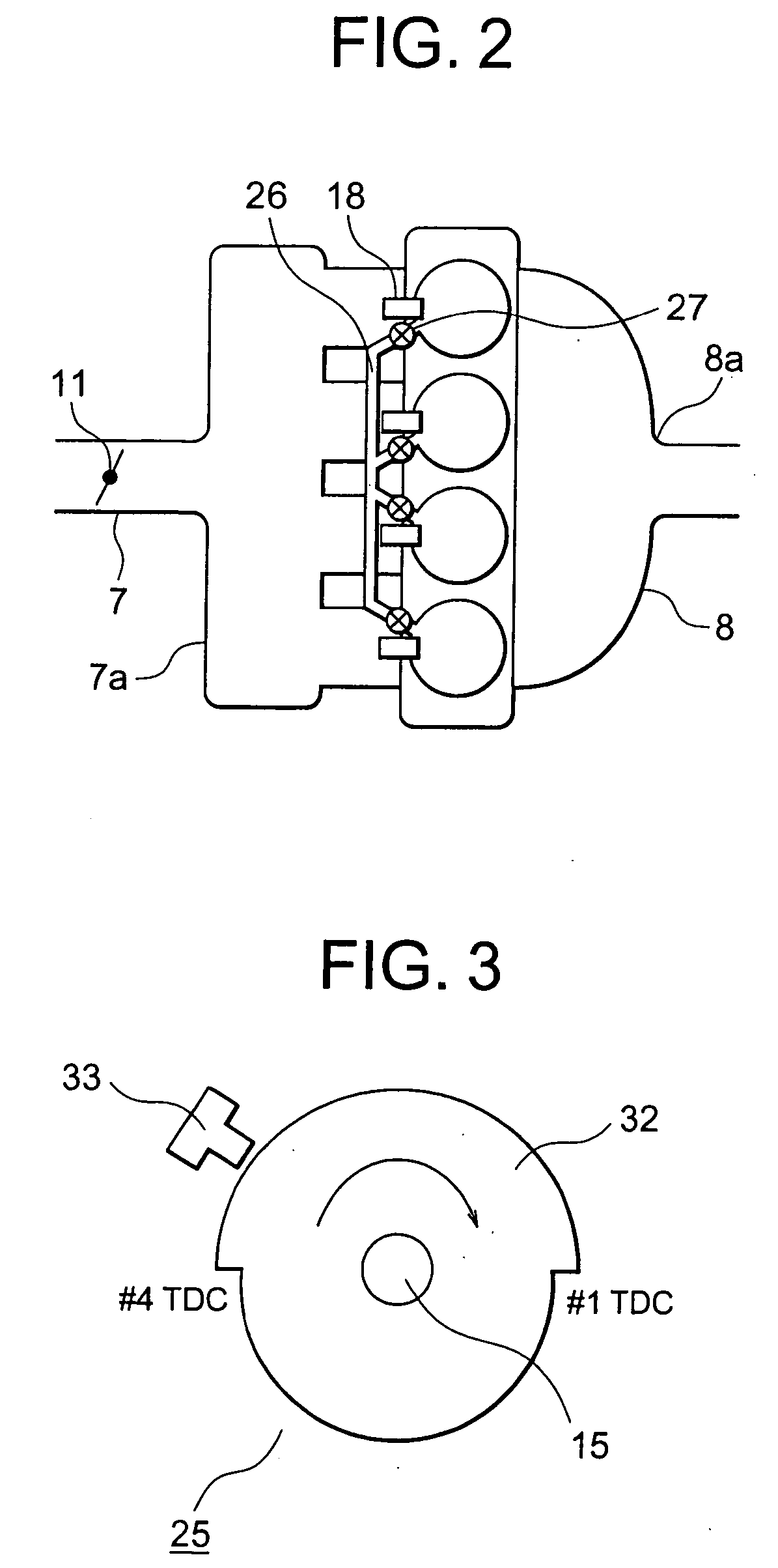
[0030]FIG. 1 is a block diagram of a four-cylinder internal combustion engine that is provided with a starting device constructed in accordance with a first embodiment of the present invention. FIG. 2 is a layout view that shows piping connecting between respective cylinders of FIG. 1 and valves (hereinafter referred to as communication control valves) for controlling the states of communication between the respective cylinders through the piping. FIG. 3 is a side elevation of a compression / expansion identification part mounted on a camshaft. FIG. 4 is a side elevation of a crank angle detector mounted on the crankshaft of the internal combustion engine. FIG. 5 is a table that shows the behaviors of respective parameters of the starting device when the engine is stopped and started, respectively. FIG. 6 shows the relation between the strokes of cylinders, a crank angle signal and a cylinder identification signal. FIG. 7 is a flow chart that shows the operational processing of the st...
embodiment 2
[0073]FIG. 11 is a block diagram of a four-cylinder internal combustion engine provided with a starting device according to a second embodiment of the present invention. FIG. 12 is a table that shows an example of the behaviors of respective parameters of the starting device of FIG. 11 when the engine is stopped and started, respectively. FIG. 13 is a flow chart that shows the operational processing of the starting device executed by an electronic engine control unit of FIG. 11 when the engine is stopped. FIG. 14 is a flow chart that shows the operational processing of the starting device executed by the electronic engine control unit of FIG. 11 when the engine is started. FIG. 15 is a flow chart that shows the operating direction determination processing of FIG. 14. FIG. 16 is a flow chart that shows the engine starting start processing of FIG. 14.
[0074] The starting device for an internal combustion engine according to this second embodiment is different from that of the above-me...
PUM
 Abstract
Description
Claims
Application Information
 - R&D
- Intellectual Property
- Life Sciences
- Materials
- Tech Scout
- Unparalleled Data Quality
- Higher Quality Content
- 60% Fewer Hallucinations
Browse by: Latest US Patents, China's latest patents, Technical Efficacy Thesaurus, Application Domain, Technology Topic, Popular Technical Reports.
© 2025 PatSnap. All rights reserved.Legal|Privacy policy|Modern Slavery Act Transparency Statement|Sitemap|About US| Contact US: help@patsnap.com


