
Communication device, cooling fan unit, and operation control method for the cooling fan unit

a technology of communication device and cooling fan, which is applied in the direction of cooling/ventilation/heating modifications, electrical apparatus casing/cabinet/drawer, lighting and heating apparatus, etc., can solve the problems of not being able to smoothly suck in cooling air and discharge cooling air when, and achieves the effect of reducing size and weight and high cooling efficiency

Active Publication Date: 2007-07-17
FUJITSU LTD
View PDF9 Cites 22 Cited by
  • Summary
  • Abstract
  • Description
  • Claims
  • Application Information

AI Technical Summary

Benefits of technology

[0010]An object of the present invention is to provide a communication device having high cooling efficiency and permitting reduction of size and weight thereof, a cooling fan unit and an operation control method for the cooling fan unit.
[0013]Further, to achieve the above object, there is provided an operation control method for a cooling fan unit having a blower fan which is fitted in a casing containing an electronic circuit board for cooling interior of the casing. The cooling fan unit operation control method comprises the step of temporarily increasing starting torque of the blower fan only for a short period of time immediately after operation of the cooling fan unit is started, to cause rotation speed of the blower fan to reach a steady-state value in an early stage after start of the blower fan.

Problems solved by technology

Also, in the case of the conventional communication device 1 in which the electronic circuit boards as a plug-in unit are positioned horizontally and arranged one above another, the cooling air cannot be smoothly sucked in and discharged when a plurality of such communication devices are mounted on a rack.

Method used


Image

  • Communication device, cooling fan unit, and operation control method for the cooling fan unit
  • Communication device, cooling fan unit, and operation control method for the cooling fan unit
  • Communication device, cooling fan unit, and operation control method for the cooling fan unit

Examples


Embodiment Construction

[0034]Embodiments of the present invention will be hereinafter described with reference to the drawings.

[0035]The invention will be described first with reference to a communication device in which a plug-in unit is mounted horizontally.

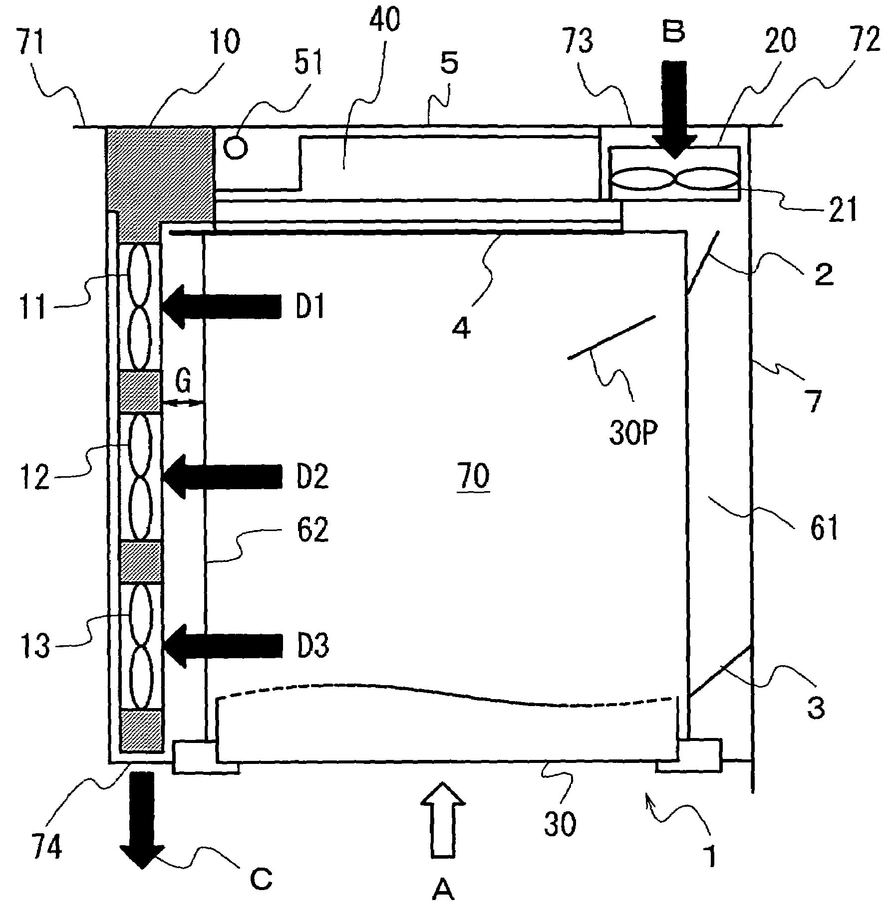
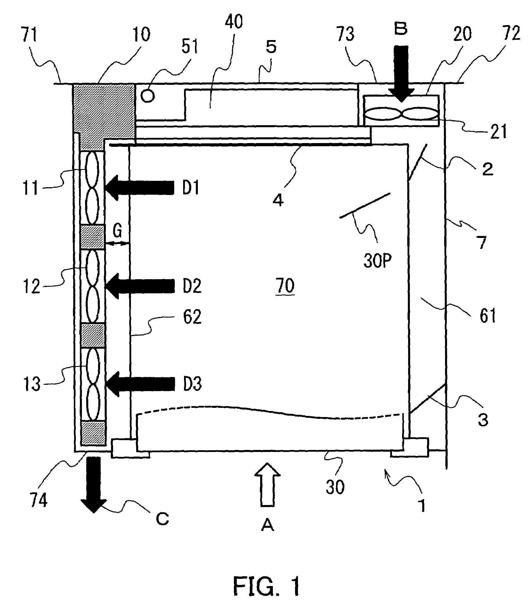
[0036]FIG. 1 is a schematic plan view of a communication device equipped with a cooling system which has a push-pull arrangement constituted by blower fans and an axial fan.

[0037]The cooling system of the communication device 1 differs in construction from the conventional cooling system in that it includes three blower fans 11, 12 and 13 as a pull-side fan unit 10. On the cooling air inlet side, however, a fan unit 20 including an axial fan 21 is used. The fan unit 20 is arranged on the right side of the back of the communication device 1, and the fan unit 10 including the blower fans 11, 12 and 13 is inserted in the left-hand portion of the communication device 1 from the back thereof.

[0038]A plurality of electronic circuit boards, for which the co...


PUM


Abstract

A communication device which has high cooling efficiency and can be reduced in size and weight. The communication device in which a plurality of electronic circuit boards are mounted to a back wiring board (BWB) includes a casing containing the electronic circuit boards as a unit, an intake fan unit for introducing air into the casing to cool the electronic circuit boards, and a discharge fan unit having a plurality of blower fans each arranged such that air intake and discharge directions thereof form an angle of nearly 90 degrees, the blower fans discharging the air introduced into the casing. Combined use of an axial fan and the blower fans permits air to be introduced into and discharged from the casing from rear and front sides, respectively, of the casing, whereby spaces that the fan units occupy in the communication device can be reduced.

Description

BACKGROUND OF THE INVENTION[0001](1) Field of the Invention[0002]This invention relates to a communication device provided with a plurality of electronic circuit boards, such as a platform information communication device, a cooling fan unit and an operation control method for the cooling fan unit, and more particularly, to a communication device comprising multiple electronic circuit boards mounted to a back wiring board (BWB).[0003](2) Description of the Related Art[0004]A conventional cooling structure for an electronic unit is disclosed in Japanese Unexamined Patent Application No. 05-259673, for example. According to this publication, a cooling system is constructed by mounting a cooling fan to an electronic unit constituted by a combination of intense heat-generating communication devices, such as electronic exchanges, such that air is forced to flow through the interior of the electronic unit. In this cooling system, the intense heat-generating communication devices are provi...

Claims


Application Information

Patent Timeline
IPC IPC(8): H05K5/00H05K7/14H05K7/20
CPCH05K7/1454H05K7/20572
Inventor UEDA, SATOSHIYAMAZAKI, NAOYAIINO, KAZUHIROSHIRAKAMI, TAKASHITADA, YOSHIAKI
Owner FUJITSU LTD
Learn More