Turbine airfoil with near-wall impingement and vortex cooling

a gas turbine engine and turbine airfoil technology, which is applied in the direction of liquid fuel engines, vessel construction, marine propulsion, etc., to achieve the effect of high internal heat transfer coefficient value, high turbulence level and maximum cooling air usag

Inactive Publication Date: 2009-03-03
FLORIDA TURBINE TECH
View PDF16 Cites 96 Cited by
  • Summary
  • Abstract
  • Description
  • Claims
  • Application Information

AI Technical Summary

Benefits of technology

[0010]This unique multi-impingement insert baffle construction cooling mechanism provides the multi-impingement cooling arrangement for the airfoil vane, maximizes the usage of cooling air for a given airfoil inlet gas temperature and pressure profile. In addition, the use of total cooling for repeating the impingement process generates extremely high turbulence levels for a fixed amount of cooling flow, and therefore creates a high value of internal heat transfer coefficient. The multi-impingement cooling process yields a higher internal convective cooling effectiveness that the single pass impingement of the prior art airfoil vane cooling design.

Problems solved by technology

In addition, the use of total cooling for repeating the impingement process generates extremely high turbulence levels for a fixed amount of cooling flow, and therefore creates a high value of internal heat transfer coefficient.

Method used


Image

  • Turbine airfoil with near-wall impingement and vortex cooling
  • Turbine airfoil with near-wall impingement and vortex cooling

Examples


Embodiment Construction

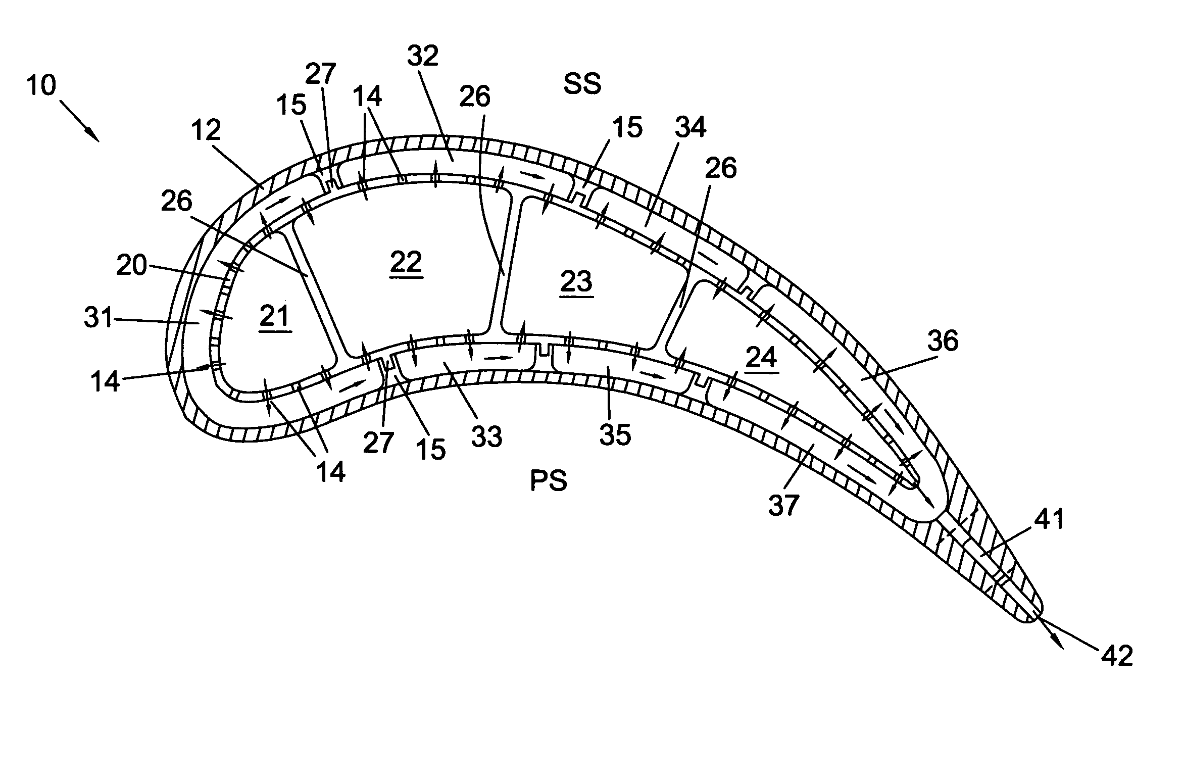
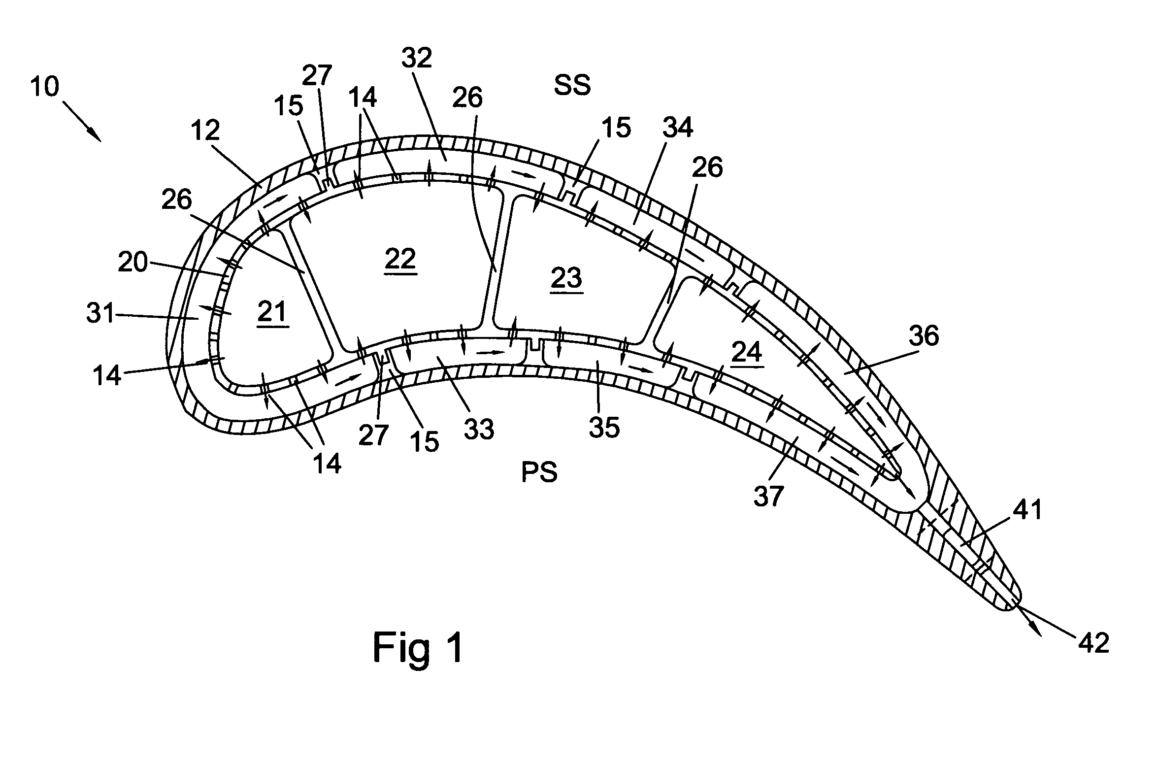
[0012]The stationary vane of the present invention is shown as a cut-away view in FIG. 1, where the vane 10 includes an outer wall 12 that forms the airfoil surface. Stand-offs 15 extends from the inner surface of the wall 12 and provides support for an insert 20. The stand-offs 15 have a groove formed therein in which a projecting member 27 of the insert fits to provide a seal. The insert 20 forms 4 impingement cavities and includes a first impingement cavity 21 located at the leading edge of the vane, a second impingement cavity 22 downstream from the first impingement cavity 21, a third impingement cavity 23 and a fourth impingement cavity 34. A fifth impingement cavity could also be formed within the insert, or the insert could have only three impingement cavities. Ribs 26 provide support for the insert 20 and form the separate impingement cavities. Each impingement cavity includes a plurality of hole to provide impingement cooling to the inner surface of the wall 12. All but th...


PUM


Abstract

An apparatus and method for impingement cooling of a turbine vane, in which the vane includes an insert having a plurality of impingement cavities formed therein and in series such that cooling air flows from a first impingement cavity onto the wall for impingement cooling, and is then directed into the second impingement cavity and redirected for impingement cooling on another part of the wall. Supports for the insert form seals that direct cooling air from one impingement cavity into the next impingement cavity in the series. A trailing edge impingement cavity directs cooling air through holes to provide impingement cooling to the trailing edge region, the cooling air passing through a trailing edge discharge passage to cool the trailing edge. The insert is formed as a single piece, and has from 3 to 5 impingement cavities separated by ribs.

Description

BACKGROUND OF THE INVENTION[0001]1. Field of the Invention[0002]The present invention relates generally to airfoils in a gas turbine engine, and more specifically to an insert located within a cooling air passage of a vane.[0003]2. Description of the Related Art Including Information Disclosed Under 37 CFR 1.97 and 1.98[0004]A gas turbine engine includes a turbine section in which a hot gas flow from the combustor passes into and reacts with multiple stages of rotor blades and stationary vanes or nozzles to extract mechanical energy from the engine. The efficiency of the gas turbine engine can be increased by providing a higher gas flow temperature. However, the temperature is limited to the materials used and the effective amount of cooling provided in the first stage of the turbine. Thus, to improve the efficiency of the engine, more effective cooling of the first stage of the turbine would be necessary if the materials used do not change. More effective use of the cooling air req...

Claims


Application Information

Patent Timeline
Patent Type & Authority Patents(United States)
IPC IPC(8): F01D5/14F04D29/38
CPCF01D5/189
Inventor LIANG, GEORGE
Owner FLORIDA TURBINE TECH
Why Eureka
Try Eureka