Insulated shipping container systems and methods thereof

a shipping container and container technology, applied in the field of shipping containers, can solve the problems of limited cooling capacity, costly upgrades to the container system, and the payload is very little cool, so as to increase the cooling efficiency, and reduce the risk of failur

Inactive Publication Date: 2010-03-23
WILLIAMS ALTON
View PDF23 Cites 113 Cited by
  • Summary
  • Abstract
  • Description
  • Claims
  • Application Information

AI Technical Summary

Benefits of technology

[0009]The present invention is generally directed to an improved insulated shipping container for shipping temperature sensitive goods and products in a refrigerated state for an extended period of time. The container system uses conventional materials arranged in a modular fashion to keep a payload cool by transferring heat from the payload to the refrigerant using the air filled space surrounding the payload and a heat transfer element, e.g. a refrigerant, as the heat transfer mechanism. During the heat transfer process the heat transfer element, or refrigerant, is in a frozen state in the process of phasing. Thus, the refrigerant phasing temperature is the refrigeration temperature for the insulated shipping container system since in the present invention the air internal to the shipping container is in contact with most of the surface area of the refrigerant and payload. Because the amount of heat transferred to or from a body is directly proportional to its surface area, the present invention increases cooling efficiency and allows higher minimum operating refrigerant temperatures, which in turn directly reduces costs, risks of failure, and improves uniform cooling. The present invention contemplates regulating the payload temperature by varying the refrigerant phasing temperature and / or varying the surface area of the refrigerant. This aspect of the invention reduces design, development and implementation cost.
[0013]When assembled, the payload is suspended from and spaced from the sidewalls of the base container creating an air filled space around the payload, which is used as the heat transfer mechanism. Additionally, the refrigerant is suspended above the payload, with substantially all of the refrigerant's surface area exposed to the air filled space such as to maximize efficiency of the heat transfer. The cooperating fit employed in the design of this preferred embodiment results in a substantially sealed container system protecting the payload from external temperatures. While the assembled base container, payload, refrigerant collar, and lid may be shipped as assembled, the components are preferably placed inside a closure carton such that the closure carton substantially surrounds the assembled components.
[0014]The present invention's design maximizes the use of heat transfer principles, i.e. convection and conduction, resulting in certain advantages including the ability to use less refrigerant per payload volume or payload weight. In addition, the design and methods of the present invention reduce the overall weight of the container system and, in turn, allows shippers to increase the amount of payload being shipped. The design and methods of the present invention also lead to increased uniformity in the cooling of the payload. The present invention also provides for the use of a single state refrigerant. Alternatively, the closure method can be taping, strapping, shrink wrapping or other closure methods known to those of skill in the art.
[0015]The present invention's modular design provides for simple construction, increasing shipping efficiency and desirability of the system. By providing a modular design, the container system lends itself to use in automated and manual distribution processes. The present invention additionally provides advantages in the ability to pre-pack payload and refrigerants in separate phases of a distribution process and allows shippers to use a variety of different refrigerant types and sizes. Additionally, the present design and methods reduce the ineffective migration of payload and refrigerant.

Problems solved by technology

Accordingly, shippers have had to make costly upgrades to their container systems to ensure compliance.
Thermal insulation is essential in protecting payloads from their thermal environment, but they do very little in keeping payloads cool.
This particular configuration is most effective in distributing small payloads and has limited cooling capacity and lack uniform cooling due to the limited contact between the refrigerant system and payload.
In order for this method to accommodate large payloads and / or greater cooling the refrigerant system must be expanded across additional payload surfaces, subsequently adding considerable weight to the container system and reducing functionality.
Added weight and burden translates to increased cost.
Ineffective refrigerant migration is another fault with this method, increasing the risk of failure.
In addition, current insulated shipping containers have seams that are susceptible to air leaks, thereby negatively impacting the insulating properties of the insulating materials and reducing the efficiency of the refrigerant.
Recent attempts to improve typical insulated shipping containers have met with mixed success.
While this design attempts to minimizes the problems associated with putting the refrigerant in direct contact with the payload, the efficiency of the refrigerant is reduced requiring the use of more refrigerant to achieve a desired cooling effect, adding to the overall cost of these types of insulation shipping containers.
In addition, the insulating properties of the refrigerant supporting tray further reduce the cooling properties of the refrigerant, requiring the use of more refrigerant and lower minimum refrigerant operating temperatures to achieve the desired cooling temperature, which in turn may lead to damage to the payload.
The designs of this and other systems, however, continue to have deleterious effects, especially with respect to the base or bottom of the payload, as there is sufficient contact between the payload and protrusions in these systems which in turn reduce air flow around critical parts of the payload, leading to uneven cooling of the payload.
Furthermore these designs continue to be costly, difficult to construct, not scalable, and not capable of being a part of a prepackaging or automated packaging system.

Method used


Image

  • Insulated shipping container systems and methods thereof
  • Insulated shipping container systems and methods thereof
  • Insulated shipping container systems and methods thereof

Examples


Embodiment Construction

will be best understood when read in reference to the accompanying figures wherein:

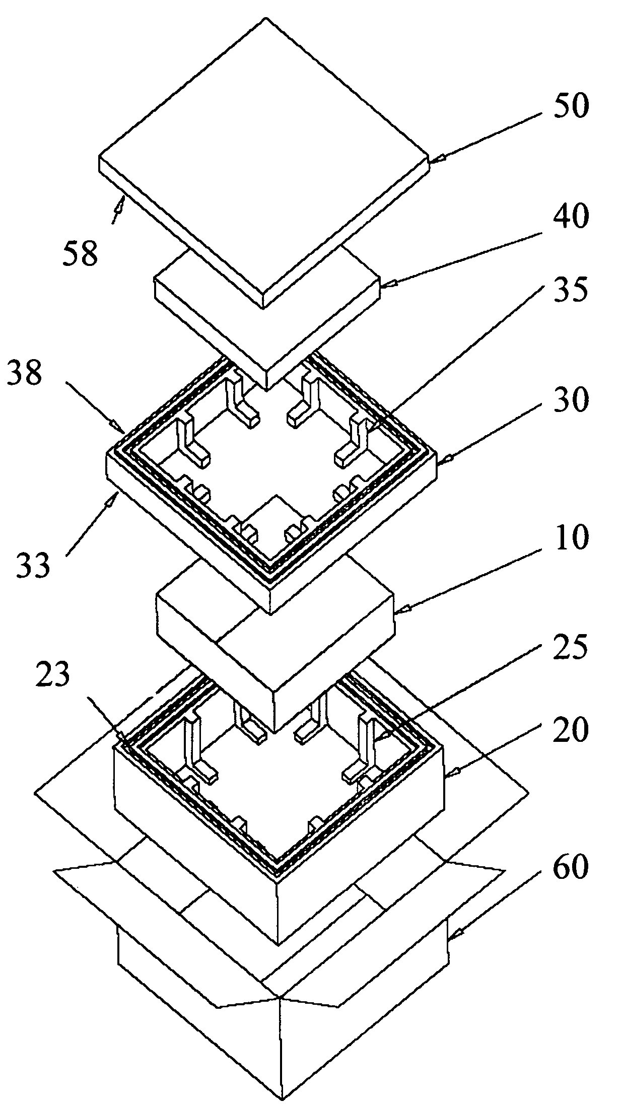
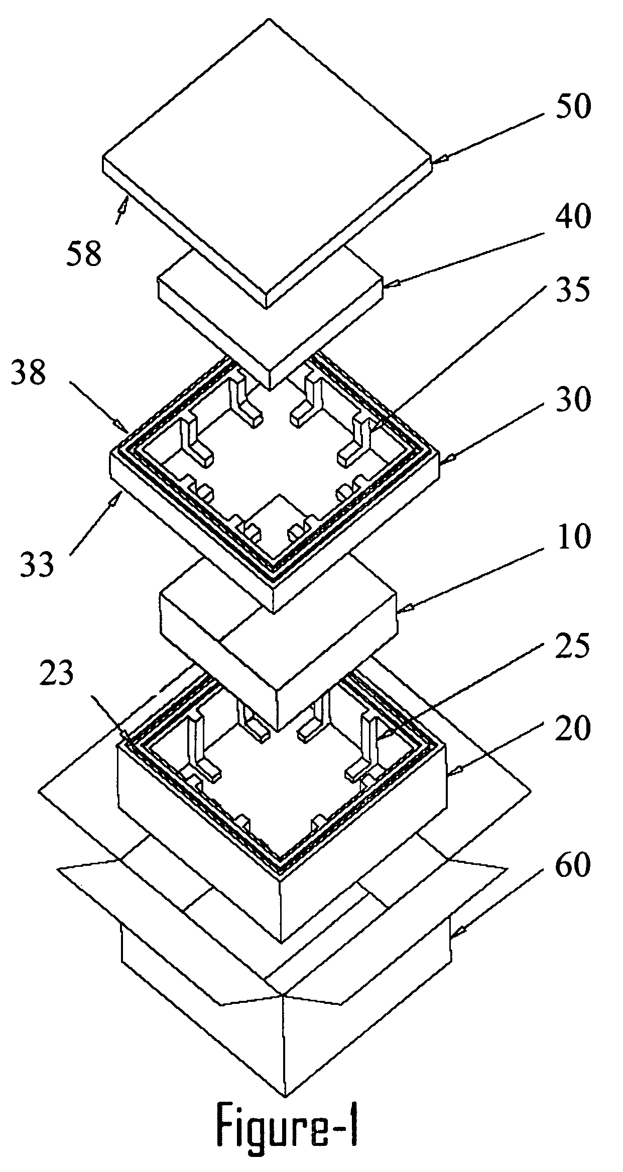
[0018]FIG. 1 is an exploded perspective view of one of the preferred embodiments of the container system;

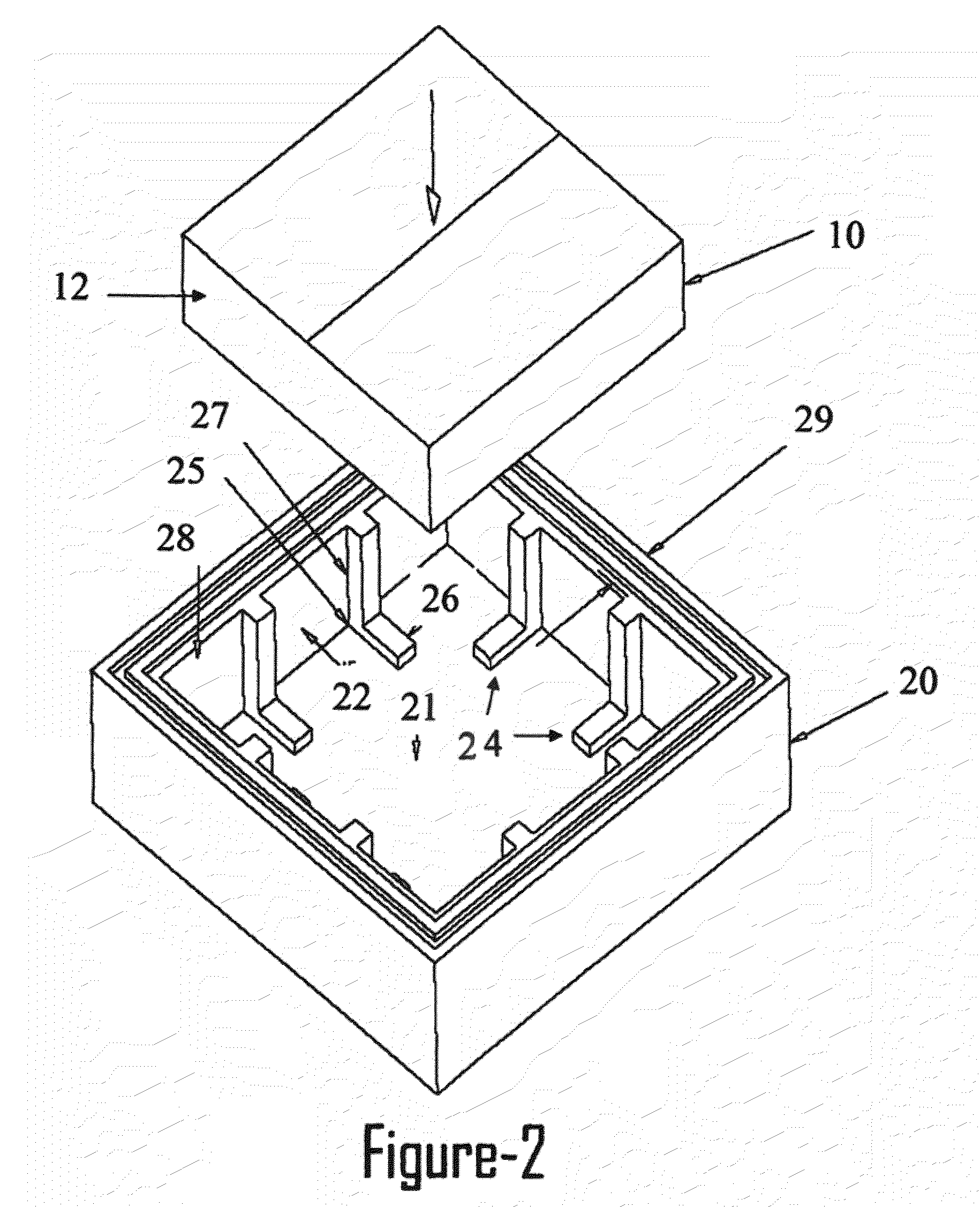
[0019]FIG. 2 is an exploded view of the base container and payload of a preferred embodiment;

[0020]FIG. 3 is an exploded view of the base container, payload, and refrigerant collar of a preferred embodiment;

[0021]FIG. 4 is an perspective view of a preferred embodiment wherein the base container, payload, and refrigerant collars have been assembled and includes a view of the refrigerant being assembled into the refrigerant collar;

[0022]FIG. 5 is a perspective view of a preferred embodiment wherein the lid is being placed onto the assembled components of the container system;

[0023]FIG. 6 is a perspective view showing a preferred embodiment wherein the assembled components are enclosed with a closure carton;

[0024]FIG. 7 is a perspective view of a preferred embodiment fully assembled;

[0025]FIG. 8 is a ...


PUM


Abstract

An insulated shipping container system for transferring a temperature sensitive product comprising a substantially hollow insulated body having inner walls and outer walls defining a payload cavity to receive a payload and supports to space the payload from the insulated body thereby defining an internal air filled space to facilitate heat transfer. The insulated shipping container system further comprises a heat transfer element cavity configured to receive a heat transfer element and supports to space the heat transfer element from the insulated body thereby defining an internal air filled space to facilitate heat transfer. Also provided are methods for shipping temperature sensitive products and goods comprised of packing and assembling the insulated shipping container system disclosed herein.

Description

FIELD OF THE INVENTION[0001]The present invention relates to a shipping container, and more particularly insulated shipping containers, used to ship temperature sensitive goods and products. The present invention also relates to methods of assembling, packing, and shipping goods and products in insulated shipping containers.BACKGROUND OF THE INVENTION[0002]Insulated shipping container systems are used to transport a variety of temperature sensitive products and goods including, for example, biological products, perishable foodstuffs, and raw materials. The thermal objective for a container system is to maintain a predetermined temperature range to protect the payload, i.e., the product being shipped from experiencing harmful external environmental temperature fluctuations, where the two most basic components are refrigerant and thermal insulation. Typical insulated shipping container systems attempt to maintain a predetermined temperature, whether cooled or heated, and attempt to in...

Claims


Application Information

Patent Timeline
Patent Type & Authority Patents(United States)
IPC IPC(8): F25D3/14
CPCB65D81/3862F25D3/08F25D2303/082F25D2303/0844F25D2331/804
Inventor WILLIAMS, ALTON
Owner WILLIAMS ALTON
Why Eureka
Try Eureka