Heat-Dissipating Structure For LED Lamp

a technology of led lamps and heat dissipation structures, which is applied in the direction of lighting and heating apparatus, lighting heating/cooling arrangements, display means, etc., can solve the problems of adversely reducing the heat dissipation efficiency of the heat dissipation device, the inability to rapidly conduct heat to the heat dissipating fin, and the increase of the contacting area. , to achieve the effect of rapid dissipation of heat to the outside, increased

Inactive Publication Date: 2008-01-10
JAFFE
View PDF14 Cites 101 Cited by
  • Summary
  • Abstract
  • Description
  • Claims
  • Application Information

AI Technical Summary

Benefits of technology

[0008]The present invention is to provide a heat-dissipating structure for a LED lamp, in which the heat can be conducted by a plurality of heat pipes, thereby to increase the contacting area. Thus, the heat can be rapidly conducted to the heat-dissipating body.
[0009]The present invention is to provide a heat-dissipating structure for a LED lamp, in which the distance from the heat pipe to the distal end of the heat-dissipating fin is reduced, thereby to rapidly dissipate the heat to the outside. Therefore, the efficiency in the heat dissipation of the whole heat-dissipating structure can be substantially increased.
[0010]One characteristic of the present invention lies in that the heat-dissipating structure is constituted of a heat-dissipating base, a heat-dissipating body and a plurality of heat pipes. The heat-dissipating body has an outer cylinder formed into a hollow cylinder. The inside surface of the outer cylinder is integrally provided with a plurality of accommodating grooves made by aluminum extrusion. The condensed ends of the plurality of heat pipes are inserted into the accommodating grooves. The end to be heated of the heat pipe is adhered to the heat-dissipating base. Further, the inside surface and the outside surface of the outer cylinder are formed with a plurality of heat-dissipating fins made by aluminum extrusion, so that the heat pipes are encircled by the heat-dissipating fins. In this way, the distance from the heat pipe to the distal end of the heat-dissipating fin is reduced.
[0011]Another characteristic of the present invention lies in that the cross section of the outer cylinder can be formed into any suitable shape, such as circle or polygon. Further, since the outer cylinder is a hollow cylinder, the air flows therethrough very smoothly. Thus, the efficiency in the heat dissipation is substantially increased.

Problems solved by technology

However, with the increase in the number of light-emitting diodes and the subsequent development of high-power light-emitting diodes, the heat generated by the operation of the light-emitting diodes is inevitably increasing.
Therefore, it is an important issue for those skilled in this art to provide a heat-dissipating structure for LED lamps.
However, the above-mentioned heat-dissipating device 10a only uses a heat pipe 104a to perform the heat dissipation, the heat cannot be rapidly conducted to the heat-dissipating fins 102a.
Further, the distance from the heat pipe 104a to the distal end of the heat-dissipating fin 102a is so long that the heat cannot be rapidly dissipated to the outside, which adversely reduces the efficiency in the heat dissipation of the heat-dissipating device 10a.

Method used


Image

  • Heat-Dissipating Structure For LED Lamp
  • Heat-Dissipating Structure For LED Lamp
  • Heat-Dissipating Structure For LED Lamp

Examples


Embodiment Construction

[0021]In order to make the Examiner better understand the characteristics and the technical contents of the present invention, the following detailed description will be made with reference to the accompanying drawings. However, it should be understood that the drawings are illustrative but not used to limit the scope of the present invention.

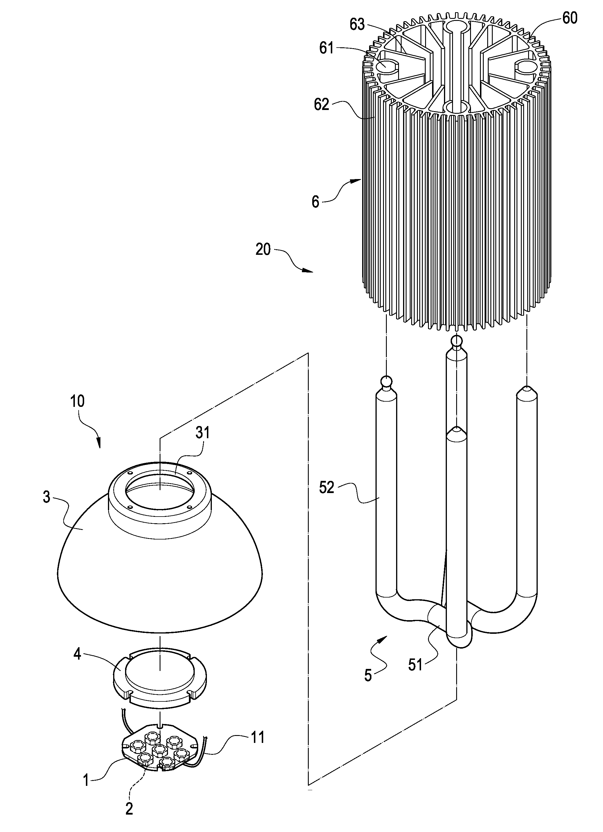
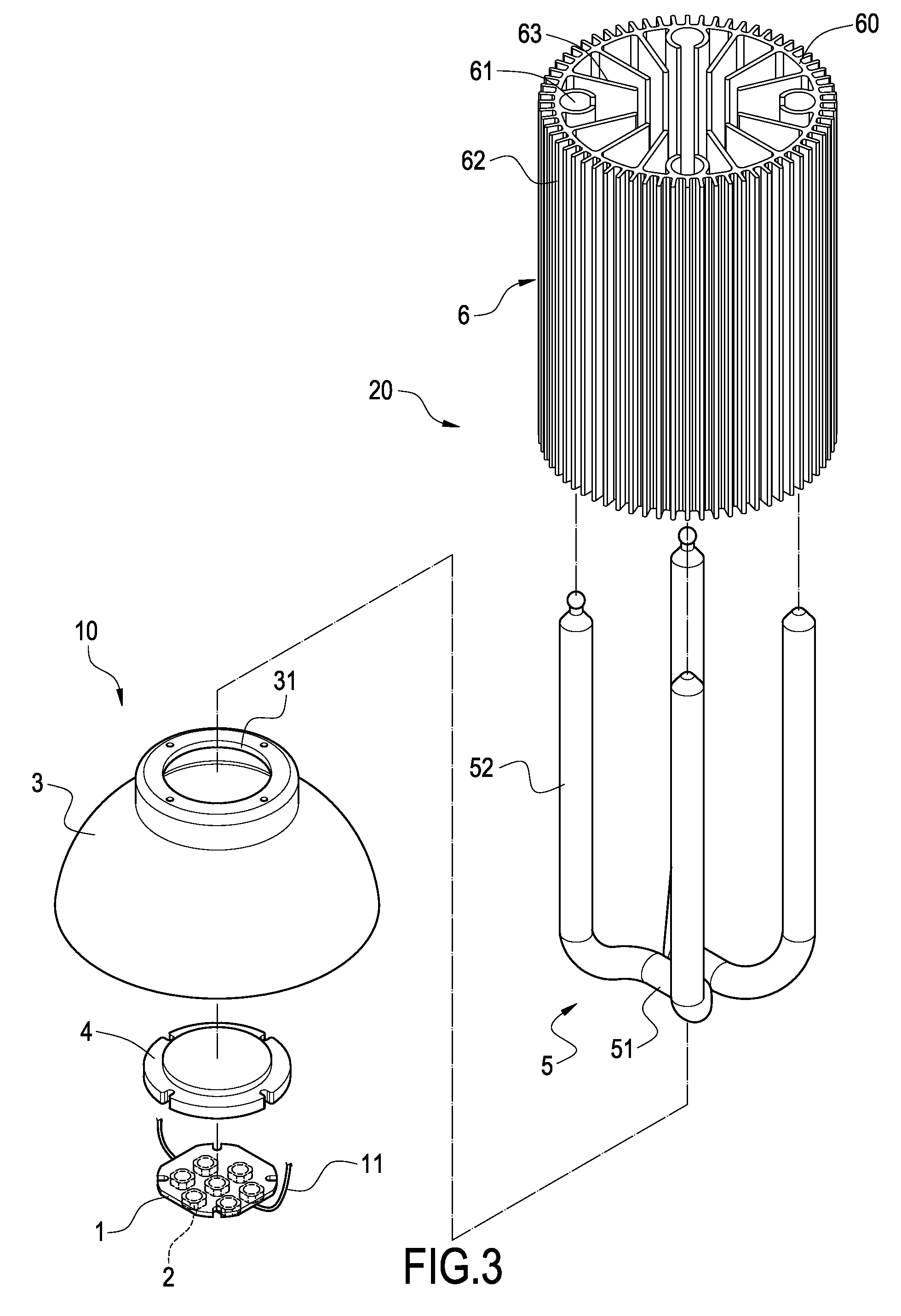
[0022]The present invention is directed to a heat-dissipating structure for a LED lamp. With reference to FIG. 3, the LED lamp 10 comprises a base plate 1 for carrying a plurality of light-emitting diodes (LED) 2 thereon. Two electric power lines 11 are connected to the base plate 1. Further, the LED lamp is provided with a lamp cover 3 formed into a bowl-like shape. Thus, the base plate 1 carrying the LEDs 2 thereon and the heat-dissipating base 4 of the heat-dissipating structure 20 of the present invention are both fixed to the bottom end of the lamp cover 3. The two electric power lines 11 penetrate through the opening 31 of the bottom end ...


PUM


Abstract

A heat-dissipating structure for a LED lamp includes a heat-dissipating base, a heat-dissipating body and a plurality of heat pipes. The heat-dissipating body has an outer cylinder formed into a hollow cylinder. The inside surface of the outer cylinder is provided with a plurality of accommodating grooves. The condensed ends of the plurality of heat pipes are inserted into the accommodating grooves. The end to be heated of the heat pipe is adhered to the heat-dissipating base. Further, the inside surface and the outside surface of the outer cylinder are formed with a plurality of heat-dissipating fins made by aluminum extrusion, so that the heat pipes are encircled by the heat-dissipating fins. In this way, the heat can be conducted by the plurality of heat pipes so as to increase the total contacting area. Thus, the heat can be rapidly conducted to the outer cylinder. Further, the heat can be rapidly dissipated to the outside by the heat-dissipating fins, thereby to substantially increase the efficiency in the heat dissipation.

Description

BACKGROUND OF THE INVENTION[0001]1. Field of the Invention[0002]The present invention relates to a heat-dissipating structure for a LED lamp, and in particular to a heat-dissipating structure capable of performing the heat dissipation of the LED lamp and substantially increasing the efficiency in the heat dissipation.[0003]2. Description of Prior Art[0004]Since light-emitting diodes (LED) are high-intensity, energy-saved and long-life, they are widely used in the illumination of electronic devices or lamps. Further, in order to increase the illuminating range and intensity thereof, a plurality of light-emitting diodes are usually combined to form a LED lamp set. However, with the increase in the number of light-emitting diodes and the subsequent development of high-power light-emitting diodes, the heat generated by the operation of the light-emitting diodes is inevitably increasing. Therefore, it is an important issue for those skilled in this art to provide a heat-dissipating struc...

Claims


Application Information

Patent Timeline
Patent Type & Authority Applications(United States)
IPC IPC(8): F21V29/00
CPCF21V29/004F21V29/006F21V29/773Y10S362/80F21V29/75F21Y2101/02F21V29/51F21Y2115/10
Inventor LI, JIA-HAO
Owner JAFFE
Why Eureka
Try Eureka