LED lamp with a heat sink assembly

a technology of led lamps and heat sinks, which is applied in the direction of lighting and heating apparatus, semiconductor devices for light sources, and support devices for lighting and heating. it can solve the problems of limited heat dissipation area of enclosures, leds to overheat, and lower heat dissipation capabilities. achieve the effect of enhancing the heat dissipation efficiency of led lamps

Inactive Publication Date: 2009-02-12
FU ZHUN PRECISION IND SHENZHEN +1
View PDF15 Cites 101 Cited by
  • Summary
  • Abstract
  • Description
  • Claims
  • Application Information

AI Technical Summary

Benefits of technology

[0008]An LED lamp includes a hollow first heat sink, a plurality of LED modules respectively mounted on outer sidewalls of the first heat sink, a second heat sink being enclosed by the first heat sink, and a plurality of heat pipes connecting the second heat sink to the first heat sink. The second heat sink includes an annular base and a plurality of fins extending outwardly and radially from an outer sidewall of the base. The heat pipes couple an inner face of the base of the second heat sink with an inner face of the first heat sink, so that heat generated by the LED modules can be transferred from the first heat sink to the second heat sink via the heat pipes, thereby enhancing a heat dissipating efficiency of the LED lamp.

Problems solved by technology

However, in order to achieve a compact design and facilitate a convenient transportation and handling of the LED lamp, the LED lamp is made having a small size, whereby the enclosure also has a small size, which leads to a limited heat dissipating area of the enclosure.
The limited heat dissipating area makes the enclosure have a lower heat dissipating capability and may cause the LEDs to overheat, whereby the LEDs will operate unstably or even fail.

Method used


Image

  • LED lamp with a heat sink assembly
  • LED lamp with a heat sink assembly
  • LED lamp with a heat sink assembly

Examples


Embodiment Construction

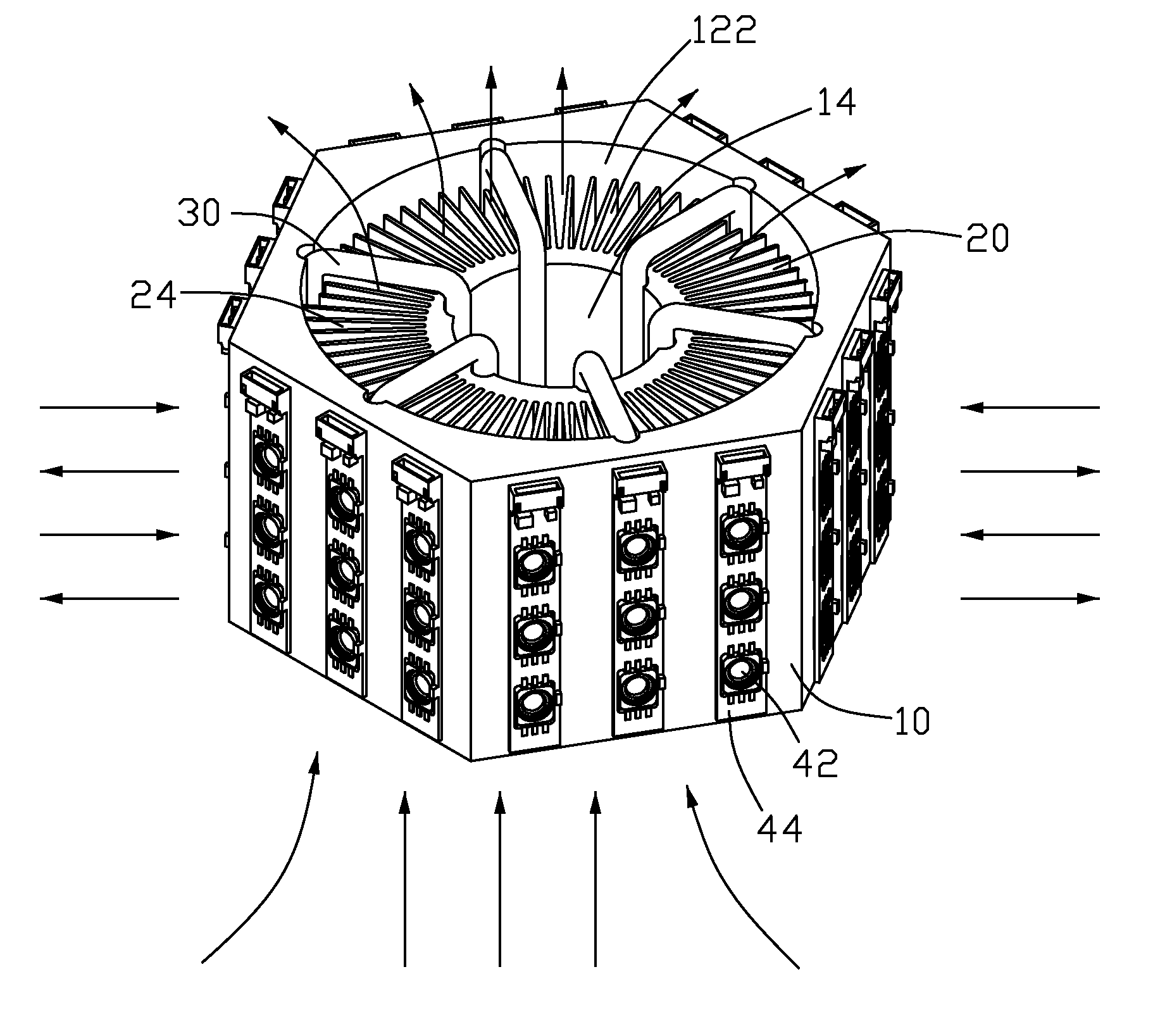
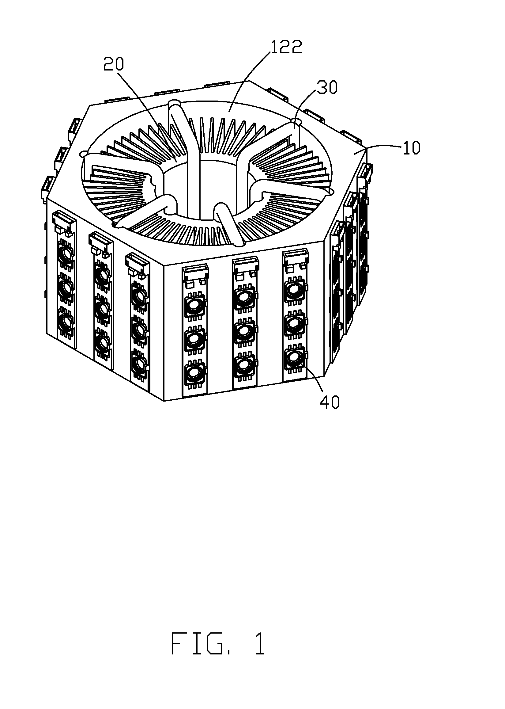
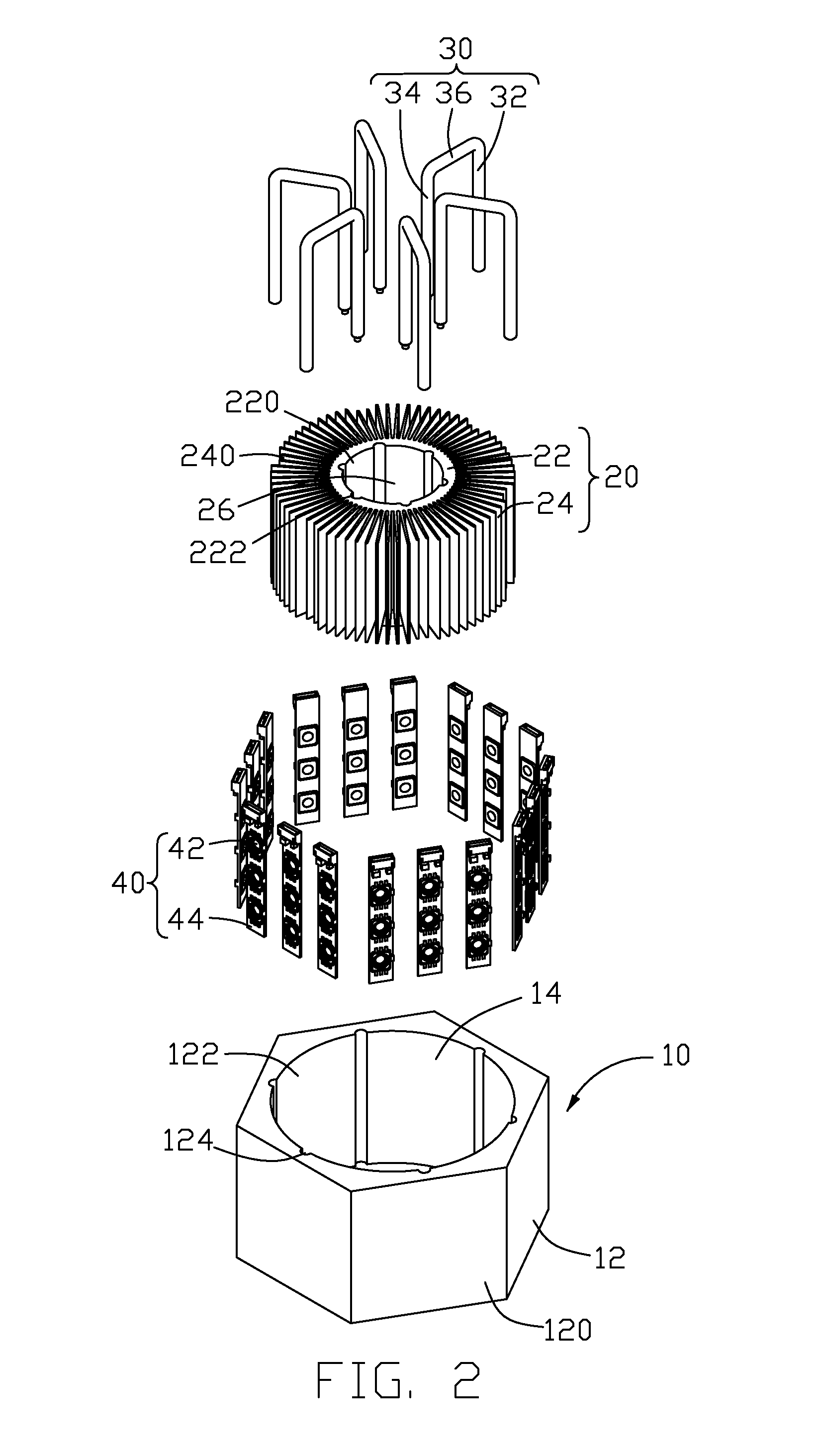
[0015]Referring to FIG. 1, an LED lamp of a preferred embodiment of the present invention comprises a first heat sink 10, a second heat sink 20 being enclosed by the first heat sink 10, a plurality of heat pipes 30 connecting the first heat sink 10 to the second heat sink 20, and a plurality of LED modules 40 mounted on a periphery of the first heat sink 10.

[0016]As shown in FIG. 2, the first heat sink 10 and the second heat sink 20 are made of metal such as aluminum, copper or an alloy thereof. The first heat sink 10 comprises a hollow hexagonal prism 12, which has six rectangular, flat and identical outer sidewalls 120. A circular through hole 14 is defined from a bottom to a top along an axis of the hexagonal prism 12 and located in a centre of the first heat sink 10, thereby defining a cylindrical inner face 122 of the hexagonal prism 12. Six straight and parallel grooves 124 each having a semi-circular cross section are evenly defined at the inner face 122 along the axis of the...


PUM


Abstract

An LED lamp includes a hollow first heat sink (10), a plurality of LED modules (40) respectively mounted on outer sidewalls (120) of the first heat sink, a second heat sink (20) being enclosed by the first heat sink, and a plurality of heat pipes (30) connecting the second heat sink to the first heat sink. The second heat sink includes an annular base (22) and a plurality of fins (24, 240) extending outwardly and radially from an outer sidewall of the base. The heat pipes couple the base of the second heat sink with the first heat sink, so that heat generated by the LED modules can be transferred from the first heat sink to the second heat sink via the heat pipes, thereby enhancing a heat dissipating efficiency of the LED lamp.

Description

BACKGROUND OF THE INVENTION[0001]1. Field of the Invention[0002]The present invention relates to a light emitting diode (LED) lamp, and more particularly to an LED lamp incorporating heat pipes for improving heat dissipation of the LED lamp.[0003]2. Description of Related Art[0004]As an energy-efficient light, an LED lamp has a trend of substituting for the fluorescent lamp for indoor lighting purpose; in order to increase the overall lighting brightness, a plurality of LEDs are often incorporated into a signal lamp, in which how to efficiently dissipate heat generated by the LEDs becomes a challenge.[0005]Conventionally, an LED lamp comprises a cylindrical enclosure functioning as a heat sink and a plurality of LEDs mounted on an outer wall of the enclosure. The LEDs are arranged in a plurality of lines along a height direction of the enclosure and around the enclosure. The enclosure defines a central through hole oriented along the height direction thereof. When the LEDs are activ...

Claims


Application Information

Patent Timeline
Patent Type & Authority Applications(United States)
IPC IPC(8): F21V29/00F21V21/00
CPCF21K9/00F21V29/004F21V29/006F21Y2101/02F21V29/83F28F1/22F28D15/0275Y10S362/80F21V29/777F21Y2111/005F21Y2115/10F21Y2107/30F21V29/51
Inventor ZHANG, WEN-XIANGYU, GUANGLAI, CHENG-TIEN
Owner FU ZHUN PRECISION IND SHENZHEN
Why Eureka
Try Eureka