
Ka-band tilt-structure active phased array antenna

A phased array antenna, tile technology, applied in the direction of the antenna, antenna array, antenna grounding switch structure connection, etc., can solve the problems of loss of phased array antenna performance, small lateral size, etc., to simplify the chip peripheral circuit and interconnection process. , the occupied space is reduced, and the effect of solving the limited horizontal space

Inactive Publication Date: 2016-08-31
10TH RES INST OF CETC
View PDF1 Cites 103 Cited by
  • Summary
  • Abstract
  • Description
  • Claims
  • Application Information

AI Technical Summary

Problems solved by technology

However, in order to solve the problem of small lateral size, some performance of the phased array antenna is lost

Method used


Image

  • Ka-band tilt-structure active phased array antenna
  • Ka-band tilt-structure active phased array antenna
  • Ka-band tilt-structure active phased array antenna

Examples


Embodiment Construction

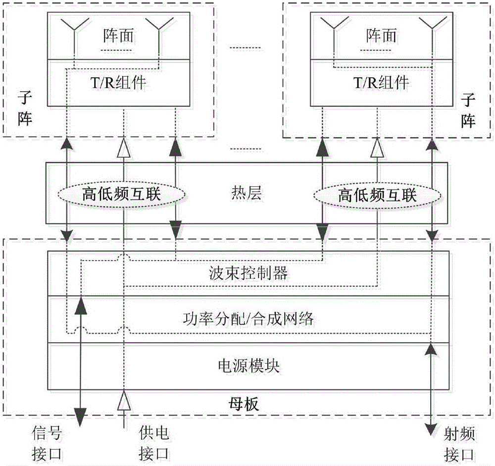
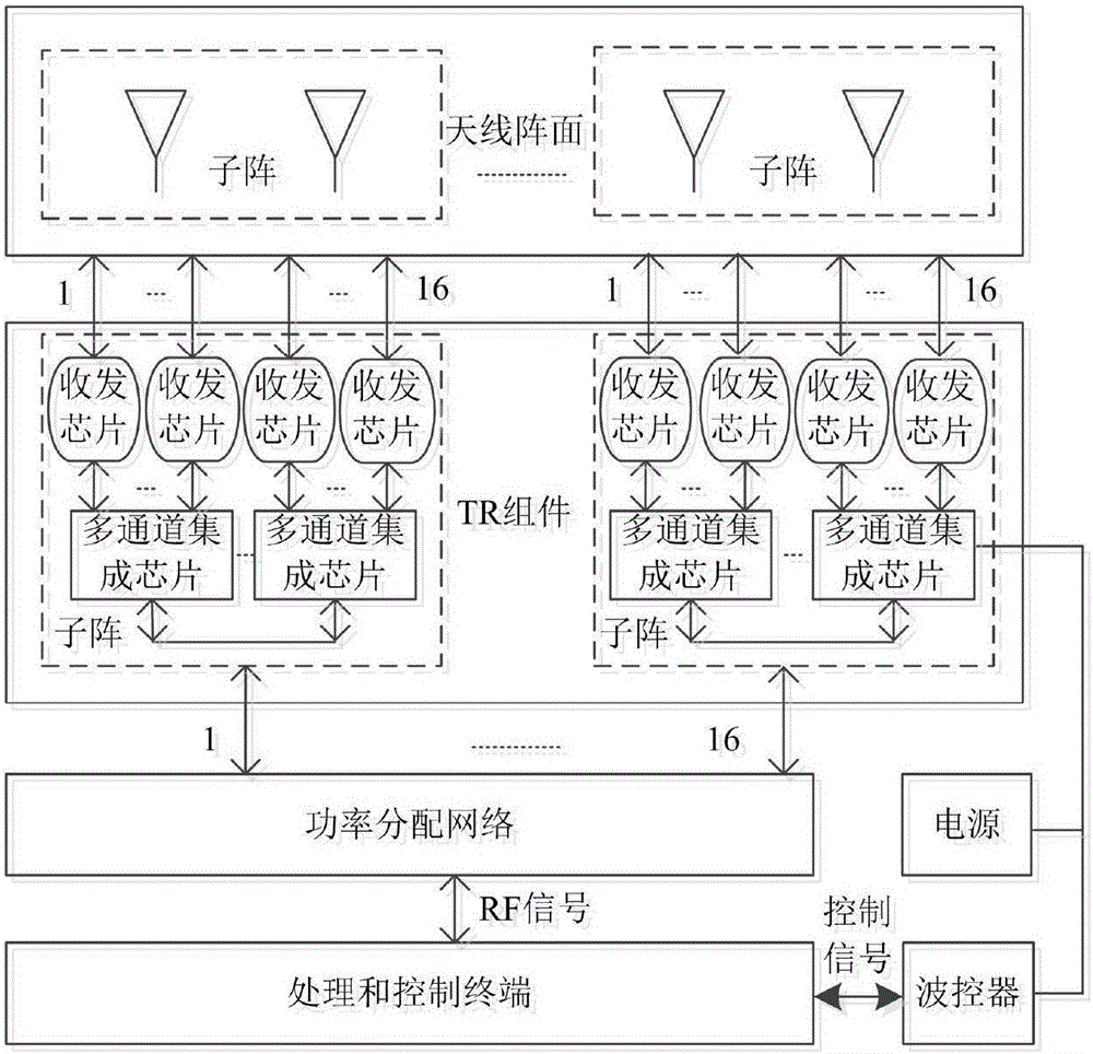
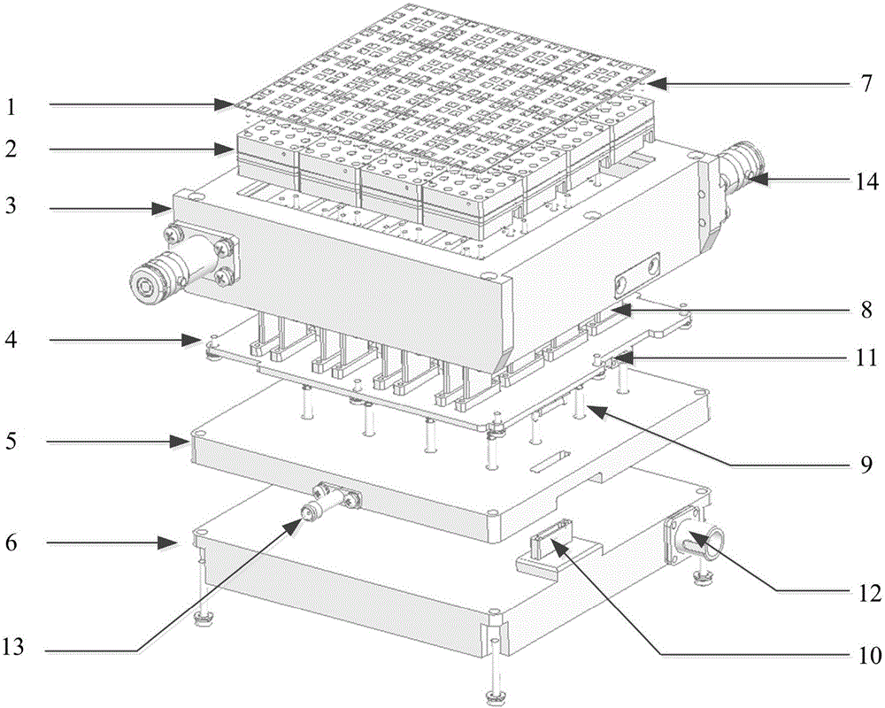
[0021] refer to figure 1 . In a best implementation case described below, a Ka-band tile-type active phased array antenna includes an active phased array composed of an antenna array 1 divided into multiple sub-arrays and a tile-type TR component 2. Antenna control tile array architecture, and each sub-array module includes N channels, each channel has an independent final-stage transceiver chip, N channels share N / L L-channel multi-functional integrated chips 20, and all sub-arrays share one set of motherboards, wherein the motherboard includes power distribution / combining network 5, beam controller 4 and power module 6, the heat sink is designed between the sub-array and the motherboard, using insulators, SMP-KK-SMP connectors, elastic Pins and multi-core high and low frequency sockets realize high and low frequency interconnection; each antenna array sub-array and tile-type TR component sub-array share a metal cavity, and the vertical interconnection conversion microstrip ...


PUM


Abstract

The invention provides a Ka-band tilt-structure active phased array antenna, so as to provide an active phased array antenna which is high in integration density and can improve maintainability and interchangeability. According to the technical scheme, one path of RF signals transmitted by a transmitting signal processing terminal are transmitted to a power distribution / synthesis network (5) via a signal interface and a radio frequency interface to be divided into M paths of signals; according to information of an azimuth angle and a pitch angle of the phased array antenna provided by the transmitting signal processing terminal in real time, a beam controller (4) calculates and obtains beam pointing of the phased array antenna in real time through an FPGA; the beam pointing of the phased array antenna is converted into phase data needed by each array element under control of the beam controller (4); the data are transmitted to tilt-type TR assembly sub array modules in N channels respectively via a high and low-frequency interconnected multi-core high and low-frequency socket, and under control of the beam controller, M*N paths of signals are transmitted to an antenna array, and thus signal transmission is completed, and synchronous electric control scanning of beams transmitted by the phased array antenna is realized.

Description

technical field [0001] The invention belongs to the field of microwave and millimeter wave technology, and relates to a Ka-band tile-structure active phased array antenna based on a multifunctional integrated chip. Background technique [0002] The prior art active phased array antennas can be classified according to structural integration methods: a "brick" structure of vertically integrated horizontal assembly (LITA) and a tile structure of horizontally integrated vertically assembled (TILA). The "brick" structure phased array antenna adopts the placement direction of components perpendicular to the aperture of the phased array antenna array, and the TR component circuit adopts the longitudinal integration horizontal assembly (LITA) method; the tile structure phased array antenna places the components in parallel In terms of the aperture of the phased array antenna, the sub-array circuit adopts the method of horizontal integration vertical assembly (TILA). The "brick" str...

Claims


Application Information

Patent Timeline
Patent Type & Authority Applications(China)
IPC IPC(8): H01Q21/00H01Q23/00H01Q1/50H01Q3/36
CPCH01Q21/00H01Q1/50H01Q3/36H01Q23/00
Inventor 陈军全何海丹何庆强
Owner 10TH RES INST OF CETC
Learn More