Serial row-select matrix-addressed system

a matrix-addressed system and serial row technology, applied in the field of matrix-addressed systems, can solve the problems of large, relatively complex integrated circuits that can require significant power, prior-art row-controller designs require large, and achieve the effect of increasing the robustness of the matrix-addressed system and high performan

Active Publication Date: 2017-06-29
X DISPLAY CO TECH LTD
View PDF6 Cites 114 Cited by
  • Summary
  • Abstract
  • Description
  • Claims
  • Application Information

AI Technical Summary

Benefits of technology

[0015]Pixels of the present invention can include pixel circuits that are formed in pixel substrates, for example, bare die or unpackaged integrated circuit substrate that are separate and distinct from the system substrate. The present invention can also include light elements formed in or on light element substrates, for example bare die or unpackaged integrated circuit substrate that are separate and distinct from the system substrate. The row-select circuit can also be formed in or on one or more row-select substrates, for example, bare die or unpackaged integrated circuit substrate that are separate and distinct from the system substrate. The separate and distinct substrates can be micro-transfer printed onto the system substrate. Alternatively, in an embodiment, the pixel substrates and the light element substrates are micro-transfer printed onto a pixel module substrates that are separate and distinct from the system substrate, the light element substrates, the pixel substrates, and the row-select substrates. The pixel module substrates can be disposed on the system substrate, for example by pick-and-place methods or micro-transfer methods. By employing micro-transfer printing methods, larger substrates with higher performance are provided in an efficient manufacturing process.
[0016]In another embodiment, redundant circuit elements, for example, redundant row storage elements, are provided to increase the robustness of the matrix-addressed system.

Problems solved by technology

Furthermore, prior-art row-controller designs require large, relatively complex integrated circuits that can require significant power.

Method used


Image

  • Serial row-select matrix-addressed system
  • Serial row-select matrix-addressed system
  • Serial row-select matrix-addressed system

Examples


Embodiment Construction

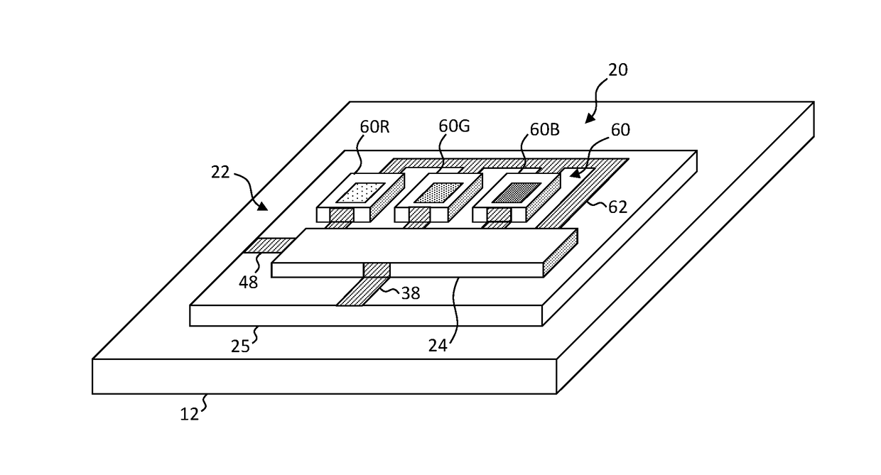
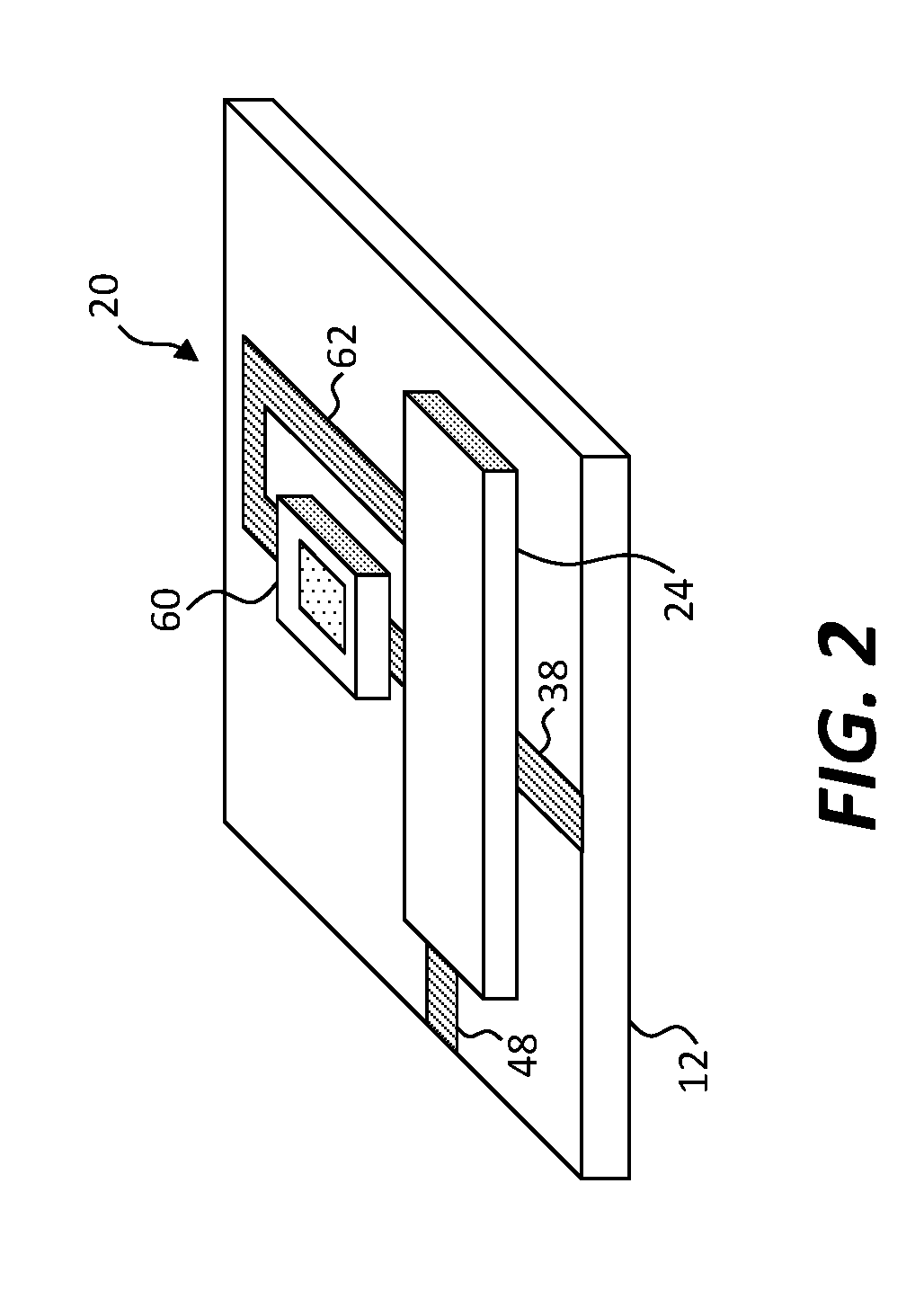
[0033]Referring to the schematic diagram of FIG. 1, a matrix-addressed system 10 of the present invention includes a system substrate 12. An array of pixels 20 are arranged in rows and columns and disposed on the system substrate 12. Each pixel 20 includes one or more light elements 60 such as light emitters or light sensors. A column-control circuit 30 provides information to the pixels 20, for example through column lines 38. The column-control circuit 30 includes a separate column-driver circuit 32 connected to each column of pixels 20; for example, through the column lines 38 that provides information in common to all of the pixels 20 in the corresponding column. A row-select circuit 40 is disposed on the system substrate 12. The row-select circuit 40 includes a serial shift register 42 having a number of row storage elements 44 equal to or larger than the number of rows in the array of pixels 20. Each row storage element 44 in the serial shift register 42 has a row-select line ...


PUM


Abstract

A matrix-addressed system includes a system substrate and an array of pixels arranged in rows and columns disposed on the system substrate. A column-control circuit provides information to or receives information from the pixels. The column-control circuit includes a separate column-driver circuit connected to each column of pixels that provides information in common to all of the pixels in the column or receives information in common from all of the pixels in the column. A row-select circuit likewise disposed on the system substrate includes a serial shift register having a number of row storage elements equal to or larger than the number of rows in the array of pixels. Each row storage element in the shift register has a row-select line connected to all of the pixels in a row.

Description

RELATED APPLICATIONS[0001]This application claims priority to and the benefit of U.S. Provisional Patent Application No. 62 / 387,259, filed Dec. 23, 2015, titled Serial Row-Select Matrix-Addressed System, the contents of which are incorporated by reference herein in its entirety.[0002]This application is related to commonly assigned U.S. patent application Ser. No. 14 / 835,282 filed Aug. 25, 2015, entitled Bit-Plane Pulse Width Modulated Digital Display System, by Cok et al. and to commonly assigned U.S. patent application Ser. No. 14 / 807,226 filed Jul. 23, 2015, entitled Parallel Redundant Chiplet System, by Cok et al. which are hereby incorporated by reference in their entirety.FIELD OF THE INVENTION[0003]The present invention relates to matrix-addressed systems such as flat-panel displays or area sensors. In particular, the present invention relates to control methods, devices, and circuits for matrix-addressing a pixel array.BACKGROUND OF THE INVENTION[0004]Flat-panel displays are...

Claims


Application Information

Patent Timeline
Patent Type & Authority Applications(United States)
IPC IPC(8): H04N5/376G09G3/3208G09G3/36
CPCH04N5/376G09G3/3611G09G2310/0221G09G2310/0286G09G3/3208G09G3/20H01L27/14601G09G2300/0426G09G2310/0267H04N25/74
Inventor COK, RONALD S.
Owner X DISPLAY CO TECH LTD
Why Eureka
Try Eureka