Starting device for internal combustion engine

Inactive Publication Date: 2005-05-31
MITSUBISHI ELECTRIC CORP
View PDF4 Cites 1 Cited by
  • Summary
  • Abstract
  • Description
  • Claims
  • Application Information

AI Technical Summary

Benefits of technology

[0007]Accordingly, an object of the present invention is to provide a starting device for an internal combustion engine which is capable of increasing st

Problems solved by technology

However, since the above-mentioned known starting devices for internal combustion engines merely reduces the compression force of a cylinder on the compression stroke, when the starting torque is to be increased for a certain purpose or when air is supplie

Method used


Image

  • Starting device for internal combustion engine
  • Starting device for internal combustion engine
  • Starting device for internal combustion engine

Examples


embodiment 1

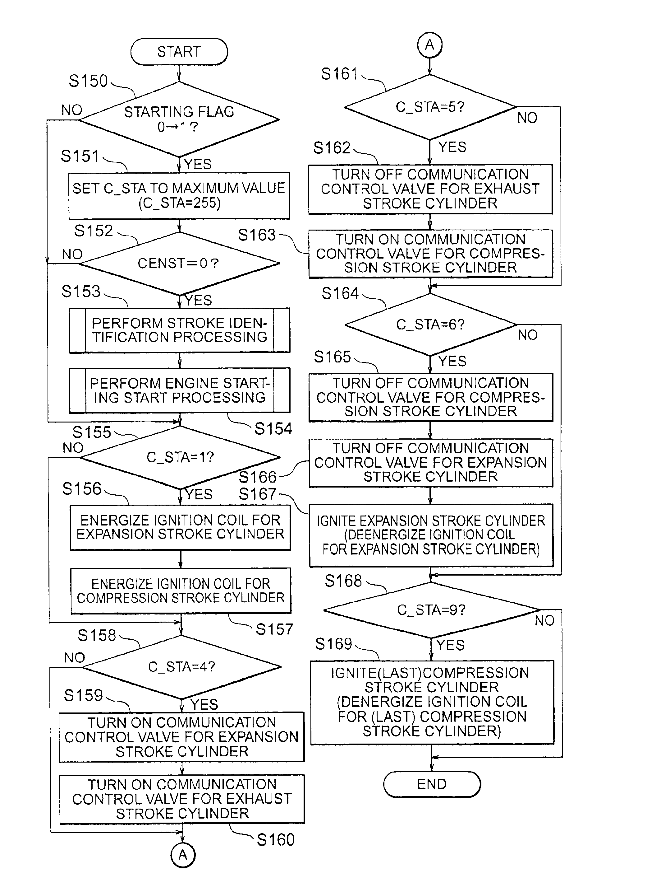
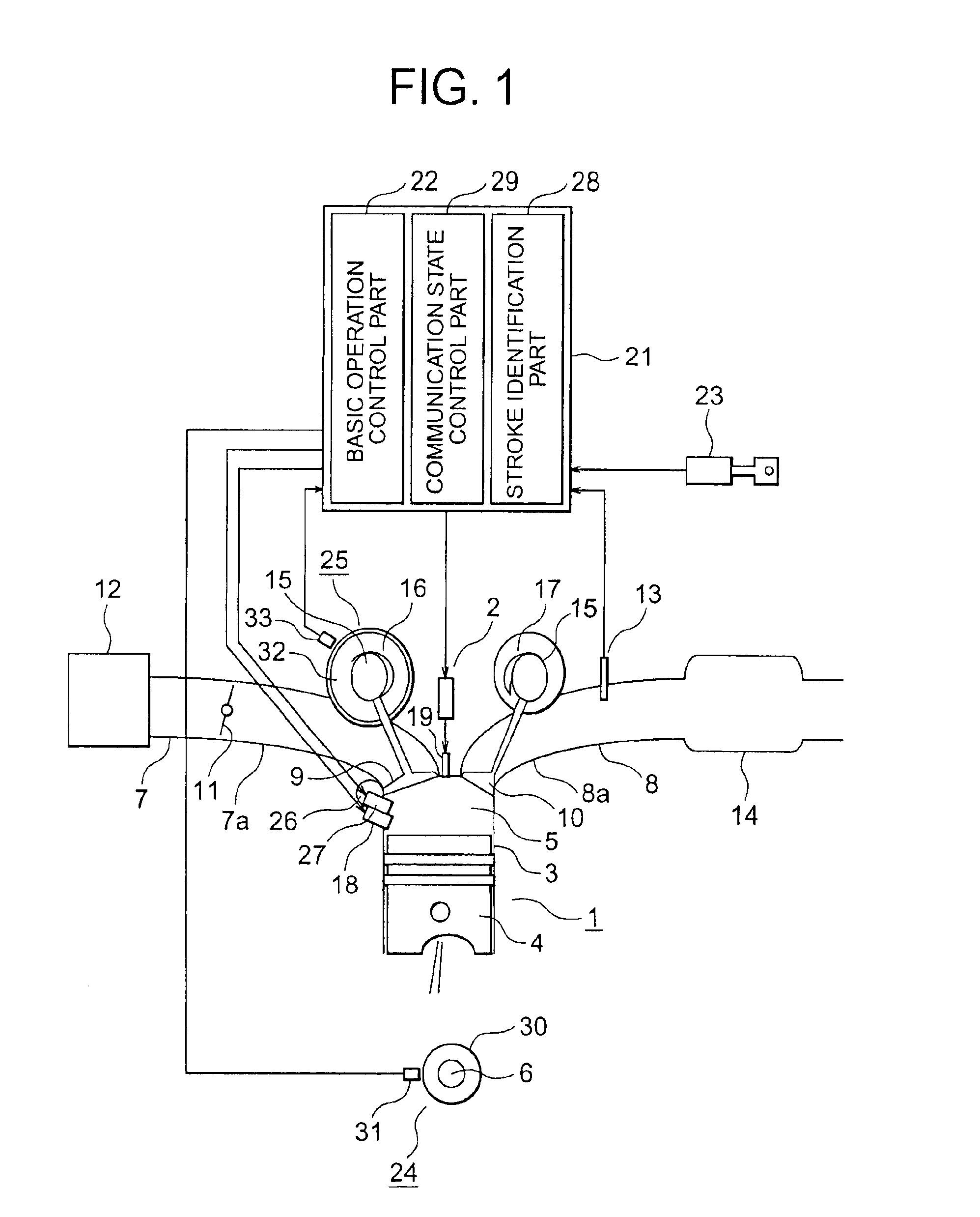
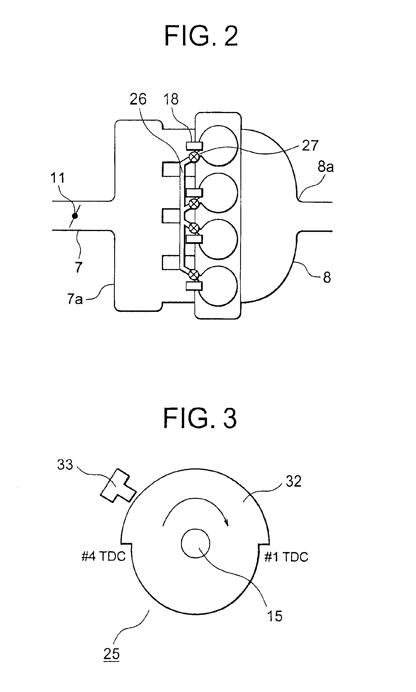
[0030]FIG. 1 is a block diagram of a four-cylinder internal combustion engine that is provided with a starting device constructed in accordance with a first embodiment of the present invention. FIG. 2 is a layout view that shows piping connecting between respective cylinders of FIG. 1 and valves (hereinafter referred to as communication control valves) for controlling the states of communication between the respective cylinders through the piping. FIG. 3 is a side elevation of a compression / expansion identification part mounted on a camshaft. FIG. 4 is a side elevation of a crank angle detector mounted on the crankshaft of the internal combustion engine. FIG. 5 is a table that shows the behaviors of respective parameters of the starting device when the engine is stopped and started, respectively. FIG. 6 shows the relation between the strokes of cylinders, a crank angle signal and a cylinder identification signal. FIG. 7 is a flow chart that shows the operational processing of the st...

embodiment 2

[0073]FIG. 11 is a block diagram of a four-cylinder internal combustion engine provided with a starting device according to a second embodiment of the present invention. FIG. 12 is a table that shows an example of the behaviors of respective parameters of the starting device of FIG. 11 when the engine is stopped and started, respectively. FIG. 13 is a flow chart that shows the operational processing of the starting device executed by an electronic engine control unit of FIG. 11 when the engine is stopped. FIG. 14 is a flow chart that shows the operational processing of the starting device executed by the electronic engine control unit of FIG. 11 when the engine is started. FIG. 15 is a flow chart that shows the operating direction determination processing of FIG. 14. FIG. 16 is a flow chart that shows the engine starting start processing of FIG. 14.

[0074]The starting device for an internal combustion engine according to this second embodiment is different from that of the above-ment...


PUM


Abstract

A starting device for an internal combustion engine is capable of increasing starting torque as well as supplying air to a cylinder that is on the expansion stroke without separately providing a means for supplying high-pressure air. Communication control valves control the states of communication between cylinders of the engine. A crank angle detector detects the crank angle of a crankshaft of the engine. A compression/expansion identification part identifies the compression stroke or the expansion stroke of each cylinder. Fuel is injected into a cylinder on the expansion stroke and ignited therein, and the expansion stroke cylinder is placed in communication with a cylinder on the exhaust stroke by a communication state control part for a prescribed time after the ignition thereof, after which the expansion stroke cylinder is further placed in communication with a cylinder on the compression stroke for a prescribed time.

Description

BACKGROUND OF THE INVENTION[0001]1. Field of the Invention[0002]The present invention relates to a starting device for staring an internal combustion engine by directly injecting fuel into cylinders of the internal combustion engine.[0003]2. Description of the Related Art[0004]A known starting device for an internal combustion engine specifies a cylinder whose piston exists in a prescribed positional allowable range or tolerance that is a considerably limited angular range after the top dead center of the piston on the expansion stroke, calculates the current pressure, temperature and volume of the thus specified cylinder, also calculates, based on the values thus calculated, an optimal pulse width for the fuel of a desired air fuel ratio to be injected into the combustion chamber of the specified cylinder through a corresponding fuel injector, and sends a signal to the corresponding fuel injector so that a desired amount of fuel can be supplied to the combustion chamber of the spec...

Claims


Application Information

Patent Timeline
IPC IPC(8): F02B23/10F02N17/00F02D13/02F02N17/08F02D41/34F02B75/12F02B75/00F02M25/07F02P13/00F02B15/00F02D15/00F02D41/06F02D43/00F02D45/00F02N19/00F02N19/06F02N99/00F02P5/15
CPCF02B23/104F02D13/0203F02D13/0253F02D13/0276F02D41/009F02M25/0723F02M25/0743F02M25/0749F02N19/00F02N99/006Y02T10/123F02D2013/0292Y02T10/125Y02T10/18F02B2075/125F02M26/20F02M26/37F02M26/43Y02T10/12
Inventor HORI, YASUYOSHI
Owner MITSUBISHI ELECTRIC CORP
Why Eureka
Try Eureka