Compressor unit and refrigerator using the unit

a compressor unit and compressor technology, applied in the direction of machines/engines, positive displacement liquid engines, lighting and heating apparatus, etc., can solve the problem of increasing starting torque, and achieve the effect of increasing starting torqu

a compressor unit and compressor technology, applied in the direction of machines/engines, positive displacement liquid engines, lighting and heating apparatus, etc., can solve the problem of increasing starting torque, and achieve the effect of increasing starting torqu

US20050103036A1Inactive Publication Date: 2005-05-19DAIKIN IND LTD

Image

  • Compressor unit and refrigerator using the unit
  • Compressor unit and refrigerator using the unit
  • Compressor unit and refrigerator using the unit

Examples


Embodiment Construction

[0023] Hereinbelow, a compressor unit of the invention and a refrigerator using the unit will be described in detail with reference to embodiments shown in the accompanying drawings.

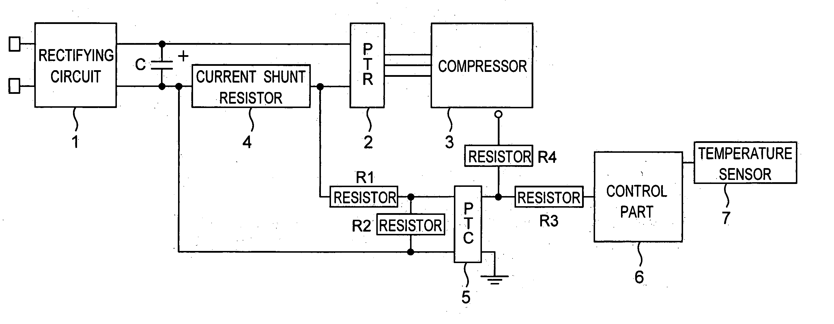
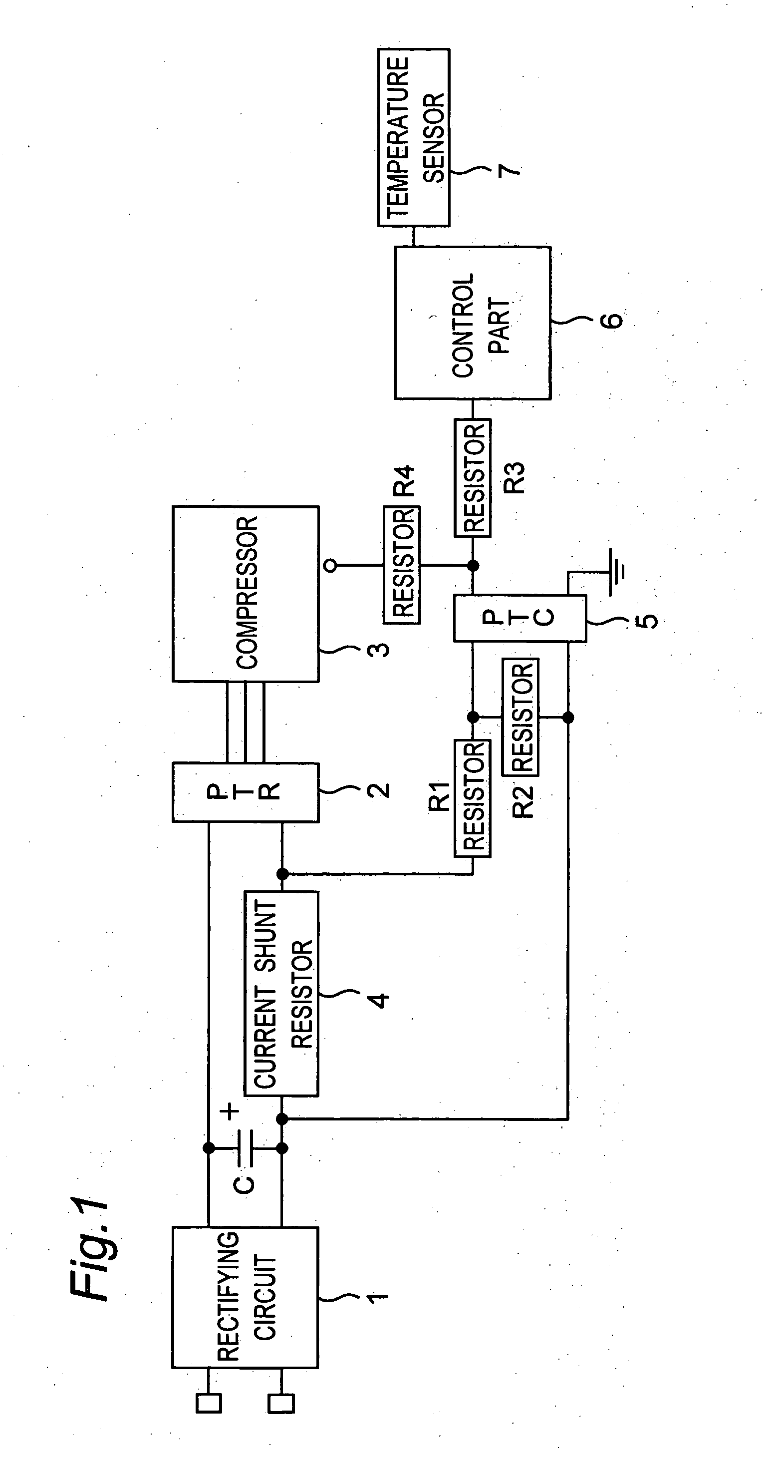
[0024]FIG. 1 is a schematic configuration of a compressor unit for use in an air conditioner in accordance with an embodiment of the invention. The compressor unit has a rectifying circuit 1 to which an AC power supply (not shown) is connected, an inverter 2 for converting a DC voltage from the rectifying circuit 1 into an AC voltage, and a compressor 3 that is driven by an output voltage from the inverter 2. An output terminal on a positive electrode side of the rectifying circuit 1 is connected to one input terminal of the inverter 2, and an output terminal on a negative electrode side of the rectifying circuit 1 is connected through a current shunt resistor 4 to the other input terminal of the inverter 2. Between both the output terminals of the rectifying circuit 1 is connected a smoothing capacitor...


PUM


Abstract

A compressor unit includes a compressor, an inverter for driving the compressor, and an over-current protective device for protecting the inverter against an output over-current. A control part controls the output voltage of the inverter when the compressor is started based on a ambient temperature detected by a temperature sensor so that the input current of the inverter does not exceed the working current value of the over-current protective device having temperature characteristics varying according to the ambient temperature. Thereby, a start torque can be increased by increasing the output voltage of the inverter without operating the over-current protective device when the compressor is stated at a low temperature when a start load is increased.

Description

TECHNICAL FIELD [0001] The present invention relates to a compressor unit and a refrigerator using the unit. BACKGROUND ART [0002] Conventionally, there has been a compressor unit that has been used in a refrigerator having refrigerant circuits. The compressor unit has a compressor, an inverter for driving the compressor, and an over-current protective device for protecting the inverter against an output over-current. When the compressor is started, an inverter output voltage is set according to a working current value of the over-current protective device. That is, the inverter output voltage is set so that an inverter output current does not exceed the working current value of the over-current protective device and so that a maximum starting torque is gained. The over-current protective device, however, has characteristics in which a high ambient temperature decreases the working current value and in which a low ambient temperature increases the working current value, as shown in ...

Claims


Application Information

Patent Timeline
19 May 2005
Publication
US20050103036A1
IPC
F04B49/06
CPC
F04B49/065; F04B2205/10; F04B2203/0202; F04B2203/0201; F04B49/00; F04B49/10
Inventors
MAEKAWA, YASUNORI