Driving System for Hybrid Vehicle

a hybrid vehicle and driving system technology, applied in the direction of electric energy management, gas pressure propulsion mounting, electric devices, etc., can solve the problems of giving an uncomfortable feeling to the driver, the battery serving as a power storage means cannot be used while being disconnected, etc., to achieve shorten the gear change time, high accuracy, and high responsiveness

Active Publication Date: 2008-12-11
NISSAN MOTOR CO LTD
View PDF1 Cites 40 Cited by
  • Summary
  • Abstract
  • Description
  • Claims
  • Application Information

AI Technical Summary

Benefits of technology

[0016]According to the invention, since power generation of the motor/generator, which has high responsiveness and high accuracy, is controlled during a gear shift operation, the rotation speed of the engine can be quickly led to a target rotation speed, and the gear change time can be shortened. Moreover, a terminal voltage of the motor/generator is increased by a step-down circu

Problems solved by technology

In the above-described hybrid-vehicle driving system, however, the battery serving as a power storage means cannot be used while being disco

Method used


Image

  • Driving System for Hybrid Vehicle
  • Driving System for Hybrid Vehicle
  • Driving System for Hybrid Vehicle

Examples


first embodiment

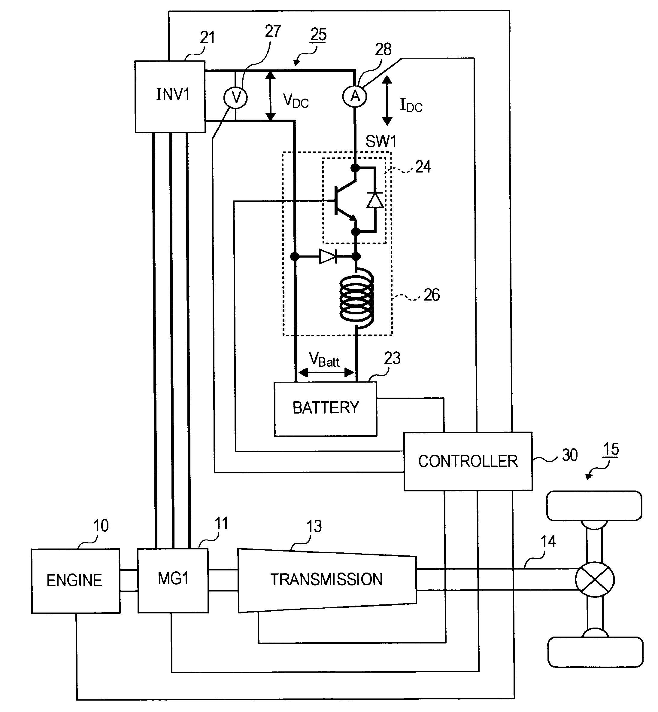
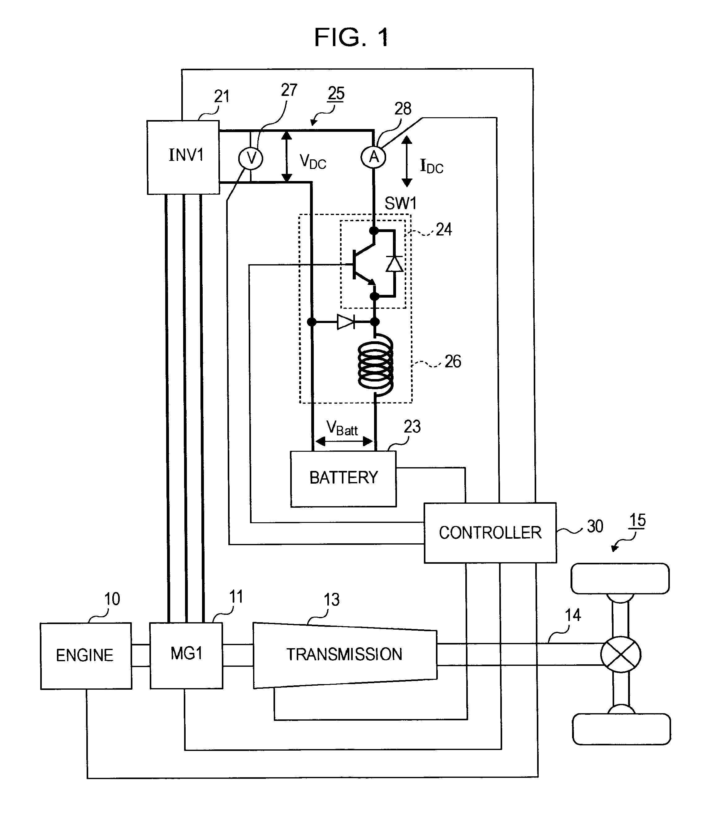
[0032]FIG. 1 is a block diagram showing the configuration of a hybrid-vehicle driving system according to a first embodiment of the present invention.

[0033]In the driving system, an engine 10 serves as a prime mover, such as an internal combustion engine, for generating a driving force. A rotation shaft of a motor / generator (hereinafter abbreviated as a MG) 11 (first motor / generator) is coupled to an output shaft of the engine 10. The MG 11 generates electric power by receiving the output of the engine 10, or generates a driving force by receiving power from a battery 23.

[0034]The rotation shaft of the MG 11 is also coupled to an input shaft of a transmission 13. The driving force input from the engine 10 and from the MG 11 is provided to the input shaft of the transmission 13 and is subjected to speed reduction (torque multiplication) according to the running condition of the vehicle, and is then output to an output shaft 14. The driving force output to the output shaft 14 is trans...

second embodiment

[0106]FIG. 11 shows the configuration of a driving system for a hybrid vehicle according to a second embodiment of the invention. Hereinafter, components having functions similar to those in the first embodiment are denoted by the same reference numerals, and the prior descriptions are incorporated herein.

[0107]A driving force from an engine 10 and a MG 11 is subjected to speed reduction via a transmission 13, and is output to an output shaft 14.

[0108]The output shaft 14 is also coupled to a rotation shaft of a MG 12 (second motor / generator). The MG 12 generates electric power during deceleration or generates a driving force by receiving power supplied from a battery 23. The driving force output to the output shaft 14 and the driving force of the MG 12 are transmitted to right and left driving wheels 15 via a differential gear, thus driving the vehicle.

[0109]An inverter 22 is provided between the battery 23 and the MG 12, and is connected at a DC terminal to the battery 23 and at an...

third embodiment

[0118]FIG. 12 shows the configuration of a driving system in a hybrid vehicle according to a third embodiment of the invention. The hybrid vehicle according to the third embodiment is different from the first embodiment in that a clutch 31 is provided between an engine 10 and a MG 11, as shown in FIG. 12.

[0119]By connecting the clutch 31 between the engine 10 and the MG 11, the driving force of the engine 10 is transmitted to an output shaft 14 via the MG 11 and a transmission 13. In contrast, the driving force from the engine 10 is interrupted by disengaging the clutch 31. In this example, transmission 13′ is preferably an automatic mechanical transmission (AMT) having a plurality of shift positions. Alternatively, a continuously variable mechanical transmission may be used.

[0120]For example, in a case in which the vehicle merges onto the highway, when the driver accelerates the vehicle to a relatively high speed. When the speed reaches a desired speed range, the driver may release...


PUM


Abstract

A hybrid-vehicle driving system includes an engine, a transmission, a first motor/generator provided between the engine and the transmission, and a battery that can charge and discharge the first motor/generator. When an estimated output voltage of the first motor/generator becomes higher than or equal to a predetermined voltage during a gear shift operation of the transmission, the battery is electrically disconnected from the driving system, and the voltage of a power line on the side of the first motor/generator is then decreased so as to charge the battery.

Description

BACKGROUND OF THE INVENTION[0001]1. Field of the Invention[0002]The present invention relates to the control and operation of a hybrid vehicle driveline.[0003]2. Description of the Related Art[0004]As a vehicle driving system, a parallel type hybrid-vehicle driving system is known in which an engine and a motor / generator are combined so that outputs of both the engine and the motor / generator can be transmitted to a driving shaft.[0005]In order to increase the output of the motor / generator, it is effective to increase the voltage to be supplied to the motor / generator. In general, however, the supply voltage is regulated by the voltage of a battery, and therefore, the output of the motor / generator normally depends on the battery.[0006]In view of this problem, Japanese Unexamined Patent Application Publication No. 10-191503 discloses a hybrid-vehicle driving system in which a battery is electrically disconnected from a hybrid system including a motor / generator, as required, so that the...

Claims


Application Information

Patent Timeline
IPC IPC(8): G06F19/00B60K6/485B60K6/547B60L50/16B60W10/06B60W10/08B60W10/26B60W20/00F02D29/00F02D29/02F02D41/04
CPCB60K6/48B60L2270/145B60W10/06B60W10/08B60W10/11B60W20/00B60W30/19F02D29/06Y02T10/6221Y02T10/6286B60L7/14B60L11/14B60L15/2009B60L2210/40B60L2220/14B60L2240/12B60L2240/421B60L2240/423B60L2240/427B60L2240/441B60L2240/443B60W10/02B60L50/16Y02T10/62Y02T10/64Y02T10/72Y02T10/7072B60W10/26B60W20/30Y02T10/70
Inventor HANYU, TOMOYUKITAKEDA, KAZUHIROKOSAKA, YUKIOOBA, HIRAKUIWANO, HIROSHIKOMIYAMA, SUSUMU
Owner NISSAN MOTOR CO LTD
Why Eureka
Try Eureka