Collision detecting device and passive safety system

a detection device and a passive safety technology, applied in the direction of instruments, force/torque/work measurement apparatus, tractors, etc., can solve the problems of large acceleration acting on the vehicle, drastic reduction of vehicle velocity, etc., and achieve the effect of eliminating the need

Inactive Publication Date: 2006-11-21
TAKATA CORPORATION
View PDF33 Cites 80 Cited by
  • Summary
  • Abstract
  • Description
  • Claims
  • Application Information

AI Technical Summary

Benefits of technology

[0018]It is an object of the present invention to provide a collision detecting device which can determine the occurrence of a collision and the magnitude of the collision (crash severity) at an early stage with high precision by detecting the collision deformation speed at ends of a vehicle body, and to provide a passive safety system using this collision detecting device. A collision detecting device of the present invention comprises a deformation speed detector for detecting a deformation speed of at least a portion around an end or side of a vehicle body. This collision detecting device can be used to activate a passive safety system on the basis of a signal.

Problems solved by technology

On the other hand, the reduction in vehicle velocity is drastic when the deformed portion has high rigidity so that the acceleration acting on the vehicle is large.

Method used


Image

  • Collision detecting device and passive safety system
  • Collision detecting device and passive safety system
  • Collision detecting device and passive safety system

Examples


Embodiment Construction

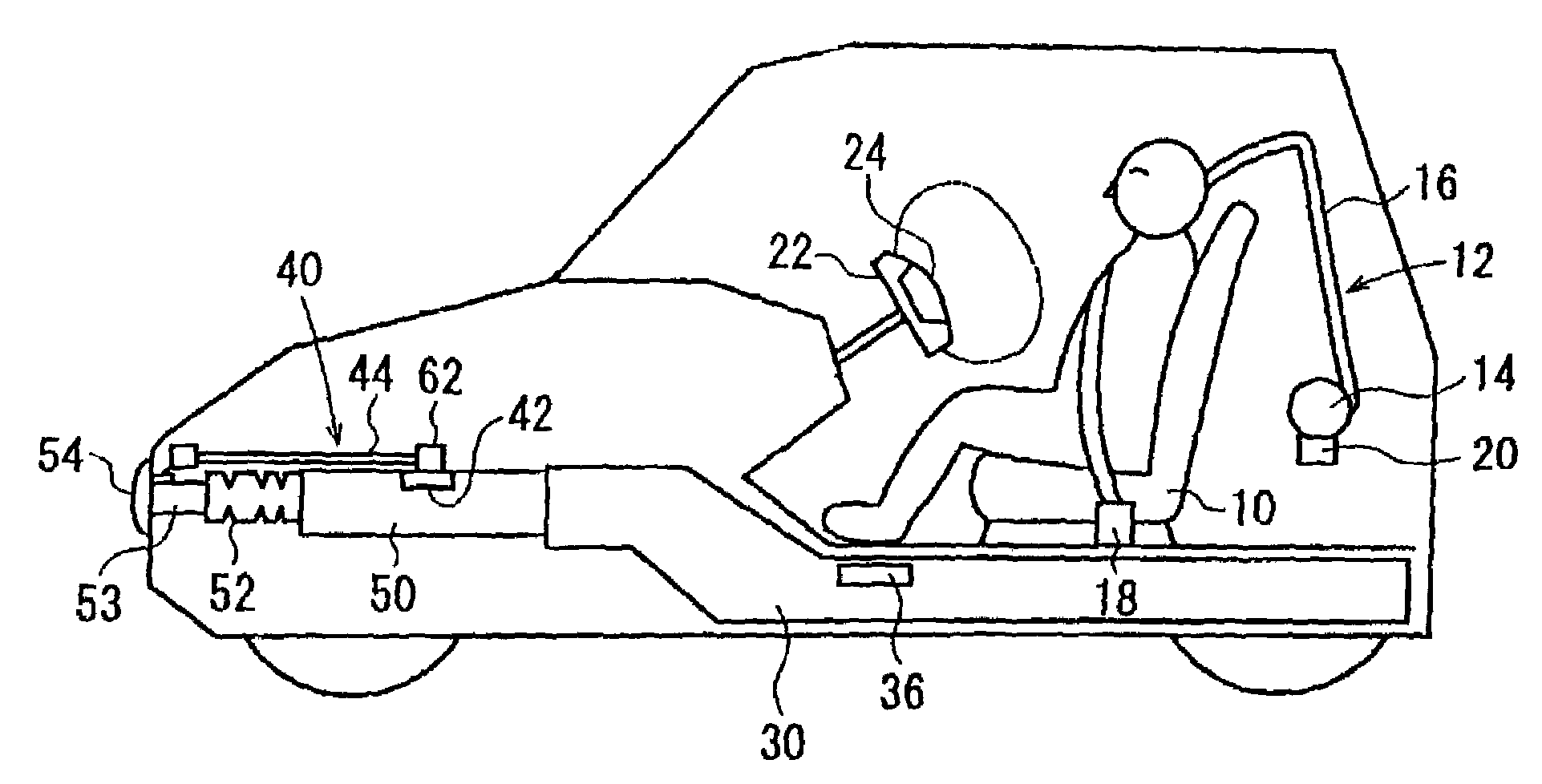
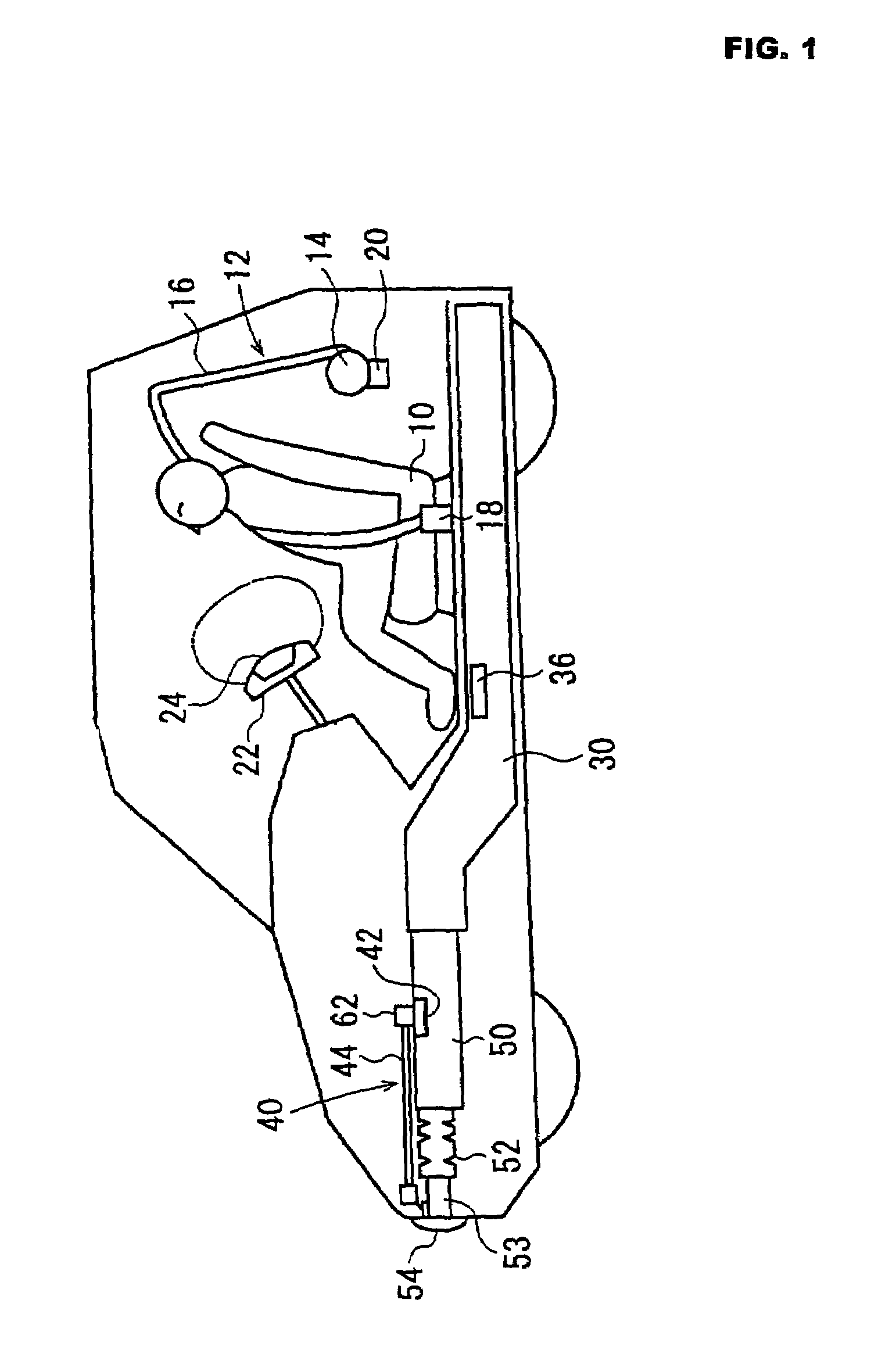
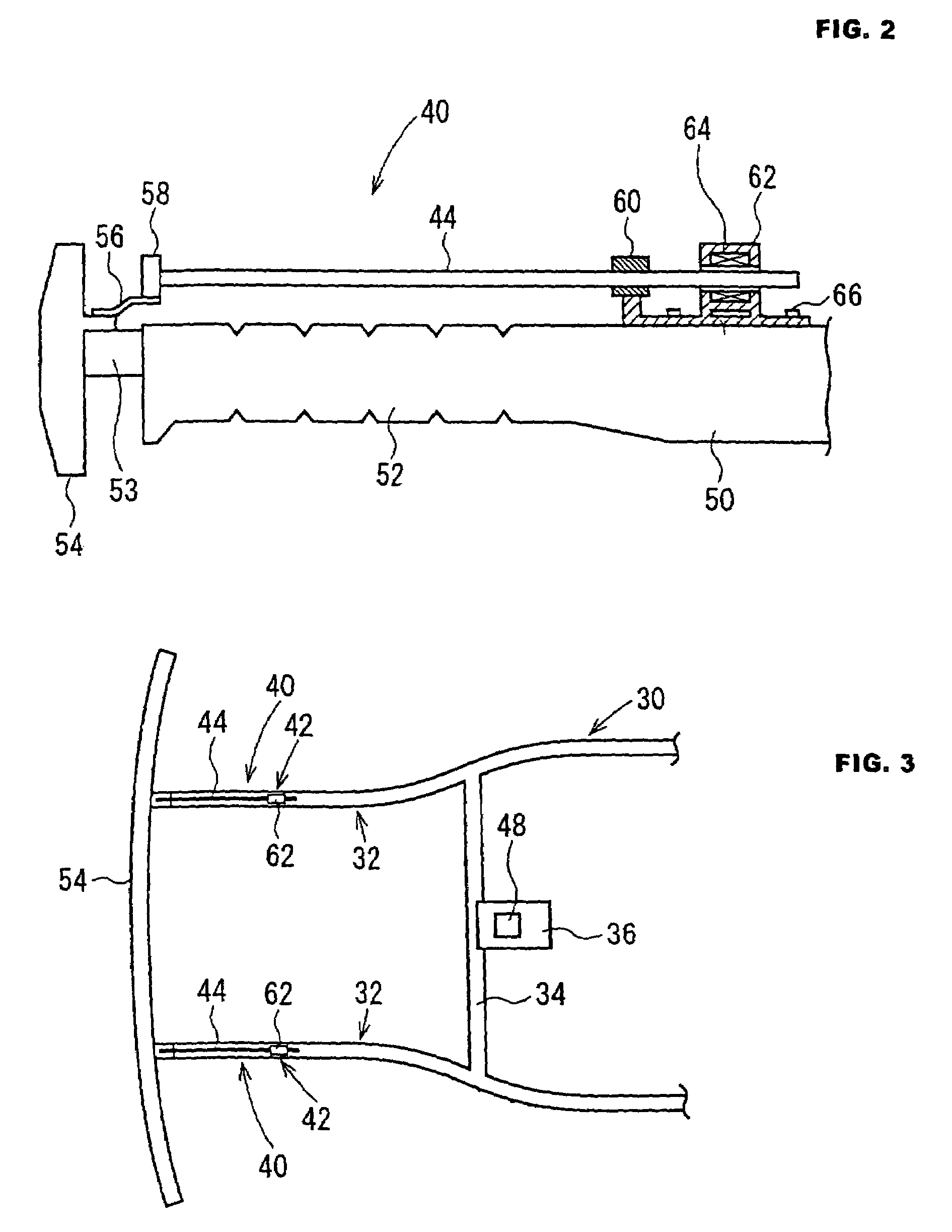
[0088]Hereinafter, embodiments of the present invention will be described with reference to the attached drawings. FIG. 1 is a schematic side view showing the structure of a vehicle equipped with a collision detecting device and a passive safety system according to the embodiment, FIG. 2 is a side view showing the structure of the collision detecting device, and FIG. 3 is a plan view showing the configuration of a front portion of a vehicle body frame.

[0089]A seat 10 is installed in a vehicle cabin of a vehicle, and a seat belt device 12 is installed for restraining an occupant sitting on the seat 10. The seat belt device 12 comprises a retractor 14, a webbing 16 to be withdrawn from the retractor 14, a buckle 18 to be latched with a tongue (not shown) for the webbing 16, and a pretensioner 20 attached to the retractor 14. The pretensioner 20 functions to rapidly wind up a predetermined length of the webbing 16 during a collision.

[0090]An airbag device 24 is installed in a steering ...


PUM

PropertyMeasurementUnit
timeaaaaaaaaaa
velocityaaaaaaaaaa
velocityaaaaaaaaaa

Abstract

A collision detecting device providing the accurate and early determination of a collision with a vehicle or the like and a passive safety system using this collision detecting device. A low-rigid portion and a crash box are arranged ahead of the high-rigid portion in a front portion of a frame. The front end of a rod is fixed to a bumper. The rod is inserted into a magnetic detector disposed on the high-rigid portion. In the rod, a number of magnets are aligned in the longitudinal direction of the rod such that their N poles and S poles are alternatively arranged. As a vehicle collides, the crash box is first deformed so that the rod moves backward, whereby a collision can be detected before large acceleration is generated.

Description

FIELD OF THE INVENTION[0001]The present invention relates to a collision detecting device for detecting a vehicle collision and a passive safety system, such as an airbag device or a seat belt device using the same.BACKGROUND OF THE INVENTION[0002]Airbag devices for protecting an occupant by inflating an airbag during a vehicle collision, and pretensioners for removing a slack of a webbing of a seat belt device by rapidly winding up a predetermined length of the webbing are well known. For activating such an airbag device or a pretensioner, it is required to determine the occurrence of a vehicle collision and the magnitude of the vehicle collision (crash severity). The crash severity correlates with the relative velocity to the object and the mass and the rigidity of the object.[0003]Conventionally, the acceleration is detected for determining the magnitude of the collision. For example, in Japanese Patent Unexamined Publication No. 11-78769, the crash severity is determined on the ...

Claims


Application Information

Patent Timeline
Patent Type & Authority Patents(United States)
IPC IPC(8): B60K28/10G01L5/00B60R19/48B60R21/00B60R21/01B60R21/0132B60R21/16G01P15/00
CPCB60R21/0136B60R21/0132B60R2021/01013
Inventor AOKI, HIROSHI
Owner TAKATA CORPORATION
Why Eureka
Try Eureka