Reconfigurable linescan illumination

a linecan and illumination technology, applied in lighting and heating apparatus, lighting support devices, instruments, etc., can solve the problems of particular challenges in the illumination of linescan cameras, and achieve the effect of improving illumination efficiency and reducing illumination costs

Inactive Publication Date: 2007-01-30
RGT UNIV OF MICHIGAN
View PDF14 Cites 14 Cited by
  • Summary
  • Abstract
  • Description
  • Claims
  • Application Information

AI Technical Summary

Benefits of technology

[0004]Illumination can be categorized as “brightfield” or “darkfield”. Brightfield illumination occurs where the camera is pointed at a region which is in the direct specular reflection from the illumination system. Darkfield illumination occurs where the camera is pointed at a region which is not in the direct specular reflection from the illumination system. In specific applications, brightfield or darkfield illumination and combinations thereof can be used to distinguish between regions of different reflection characteristics in the scene, which aids in recognizing boundaries, different materials, geometries or surface characteristics.
[0007]There is, therefore, a need for an improved illumination system, which can handle different linescan illumination applications, and can reduce cost and integration time.SUMMARY

Problems solved by technology

Different illumination solutions for linescan cameras are particularly challenging due to the high aspect ratio of the acquired line.

Method used


Image

  • Reconfigurable linescan illumination
  • Reconfigurable linescan illumination
  • Reconfigurable linescan illumination

Examples


Embodiment Construction

[0015]The following description is merely exemplary in nature and is in no way intended to limit the invention, its application, or uses. For example, although the present teachings are particularly illustrated for the manufacturing applications of surface defect inspection and dimension measurement, the present teachings can be used for machine vision or other visual inspection processes in the context of any manufacturing process.

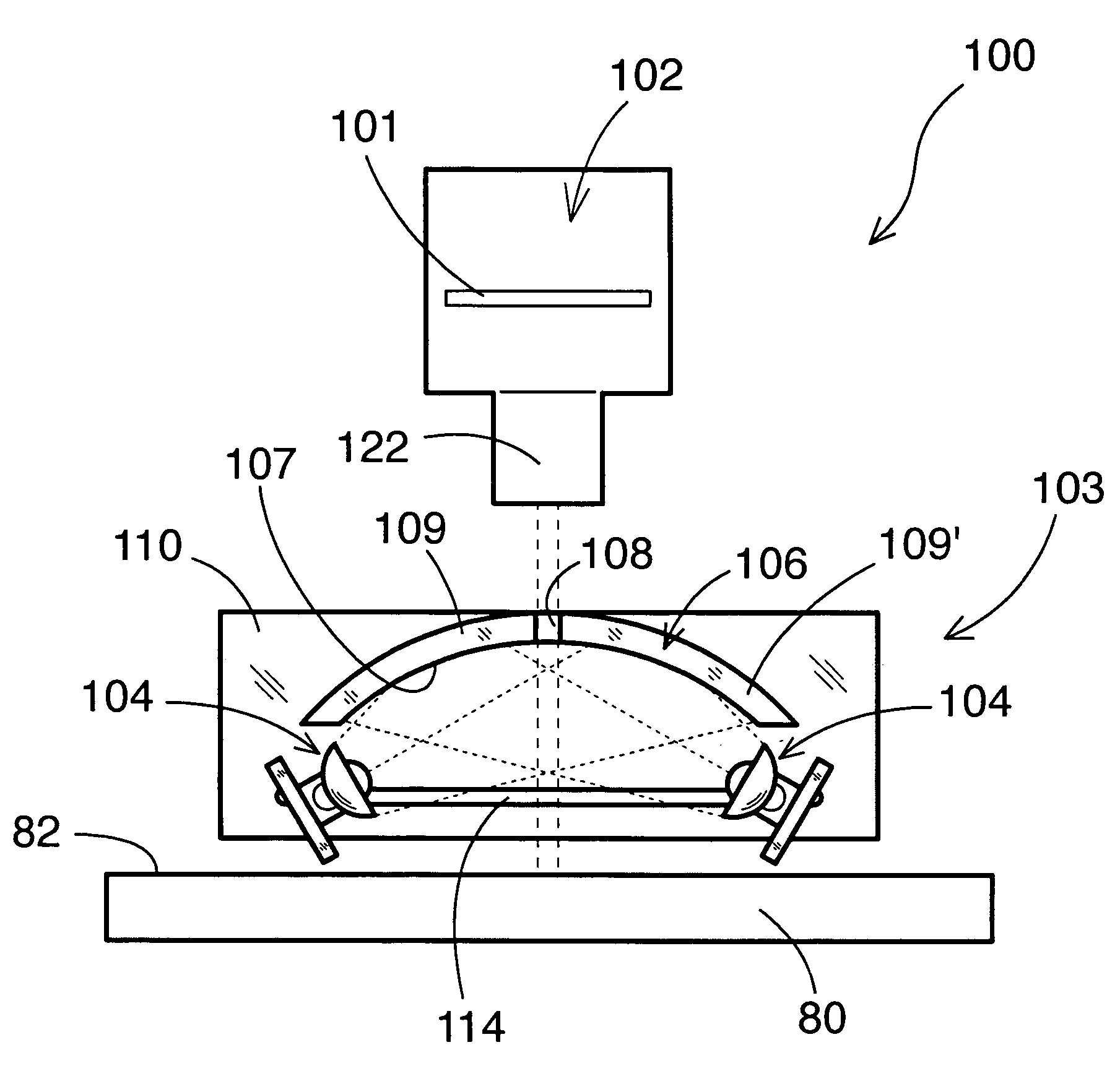
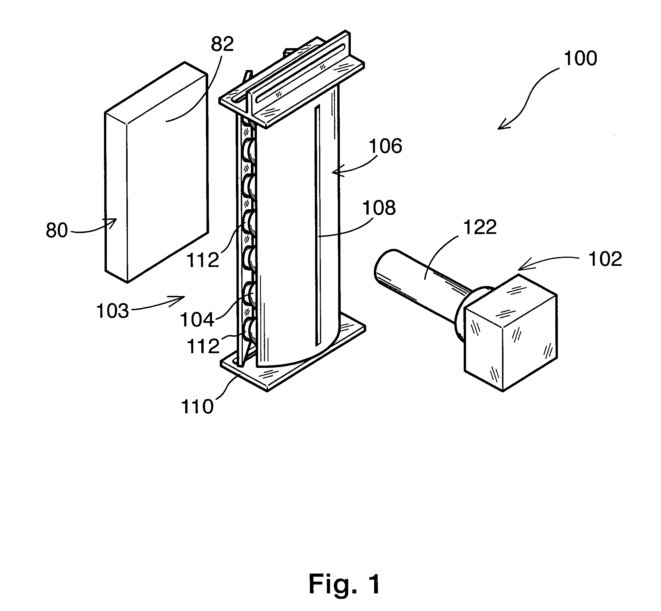
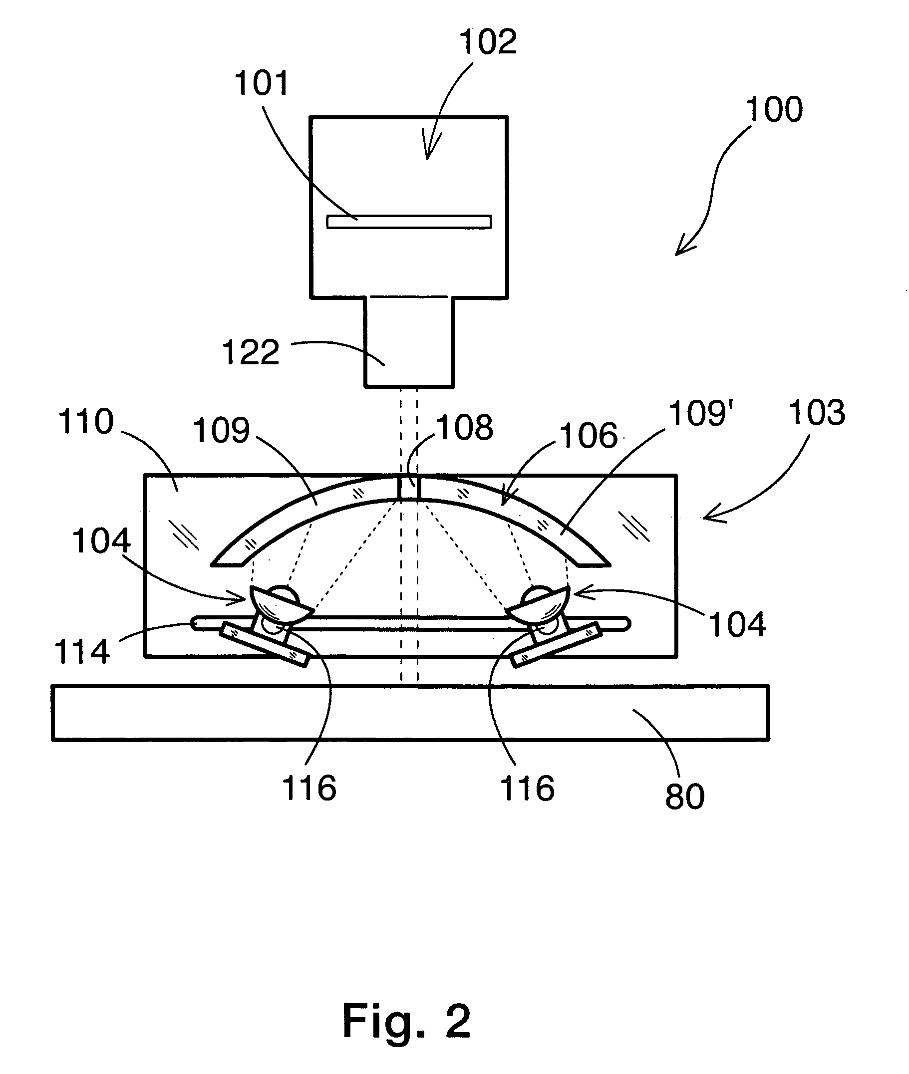
[0016]Referring to FIGS. 1 and 2, an exemplary reconfigurable illumination system 100 according to the present teachings may include a linescan camera 102 that has a lens 122 and a sensor array (or sensor) 101, an illuminator 103 that includes one or more light sources 104, and a cylindrical diffuser 106 that has a longitudinal aperture 108. The diffuser 106 can include two equal portions 109, 109′ separated by the longitudinal aperture 108 through which the camera 102 views a surface 82 of a part or object 80. The diffuser 106 can be modular, such that t...


PUM


Abstract

A reconfigurable illumination system for illuminating an object, and associated method. The illumination system comprises a cylindrical diffuser having a longitudinal aperture, a linescan camera positioned for having a direct line of sight to the object through the aperture of the diffuser, a base, and an illuminator supported on the base and positioned between the diffuser and the object, wherein the illuminator is selectively reconfigurable in a plurality of configurations, each configuration corresponding to a manufacturing process that requires visual inspection of the object.

Description

FEDERALLY SPONSORED RESEARCH[0001]Certain of the research leading to the present invention was sponsored by the United States Government under National Science Foundation Grant No. EEC-959125. The United States Government has certain rights in the invention.INTRODUCTION[0002]A machine vision system is typically a system able to extract data about a scene, using images captured by a camera. A scene is defined as part of the world which is within the visual field viewed by the camera. An image is a two-dimensional projection of a scene.[0003]A machine vision system can be used for manufacturing processes to extract relevant information about the quality of a manufactured object or a manufacturing process. Illumination is an important component of any machine vision system because the ability of the system to capture images and extract data depends on the quality of the illumination.[0004]Illumination can be categorized as “brightfield” or “darkfield”. Brightfield illumination occurs w...

Claims


Application Information

Patent Timeline
Patent Type & Authority Patents(United States)
IPC IPC(8): F21V33/00
CPCG01N21/8806
Inventor ABRAMOVICH, GILWARLICK, ZACHARYKOREN, YORAM
Owner RGT UNIV OF MICHIGAN
Why Eureka
Try Eureka