Ganged outlet power distribution apparatus

a power distribution apparatus and power outlet technology, applied in the direction of substation/switching arrangement casings, substation/switching device connections, support structures, etc., can solve the problems of limiting the size and shape of the housing, the design of the rack may limit the degree of connection of the power distribution unit to the frame of the rack itself, and the inefficiency of many problems, so as to reduce the amount of interior space and more room for electrical components and associated wiring

Inactive Publication Date: 2007-09-11
SERVER TECHNOLOGY
View PDF34 Cites 124 Cited by
  • Summary
  • Abstract
  • Description
  • Claims
  • Application Information

AI Technical Summary

Benefits of technology

[0016]The above embodiments may provide a number of advantages. For example, the size of a power distribution unit may be reduced because each outlet no longer needs to be connected by standard, flexible wires. Because of the reduced number of parts, these embodiments may provide other advantages, such as faster assembly, fewer assembly errors, and enhanced reliability. One or more of these advantages may reduce the cost of manufacturing the power distribution units.
[0027]In additional embodiments, the power distribution unit may have access openings. The access opening may allow access to, or visual inspection of, certain components of the power distribution unit, such as fuses. Further embodiments provide a separate component, such as a light source, which indicates the status of a fuse or similar device. In this way, an operator may visually determine whether a fuse has blown without having to remove or disassemble the power distribution unit. In addition, in certain embodiments, the operator may replace the fuse without having to remove or disassemble the power distribution unit. In at least one embodiment, the power distribution unit is constructed so that an access opening may be provided on a selected side of the power distribution unit during assembly. In additional embodiments, the access openings may be covered, including by transparent windows or by protective coverings such as metal or plastic plates.

Problems solved by technology

The design of the rack may limit how closely a power distribution unit may be mounted to frame of the rack itself.
Typically, all of these electronic components must be wired together, which can create numerous problems and inefficiencies.
One such problem is that the size of the electronic components and the associated wiring may limit the dimensions and shape of the housing.
The size of the housing can limit the location in which the power distribution unit can be mounted.
For example, the power distribution unit may be too large for certain spaces.
The size of the components and wiring may limit how many and what kind of components can be included in a power distribution unit.
Such prior art power distribution units often require substantial time and effort to assemble because each electronic component is typically individually mounted in the housing.
The cost to build such devices may be influenced by material costs that are partially determined by factors such as the size of the housing, the amount of wiring in each device, and the amount of other materials, such as solder, needed to assemble each power distribution unit.
In addition to possibly requiring greater assembly time, the numerous parts and connections in typical prior art power distribution units may result in a greater number of errors during the manufacturing process or a greater chance of equipment failure once the power distribution units are in use.
In addition to possibly being time consuming and labor intensive, opening up the unit may violate a warranty on the unit.

Method used


Image

  • Ganged outlet power distribution apparatus
  • Ganged outlet power distribution apparatus
  • Ganged outlet power distribution apparatus

Examples


Embodiment Construction

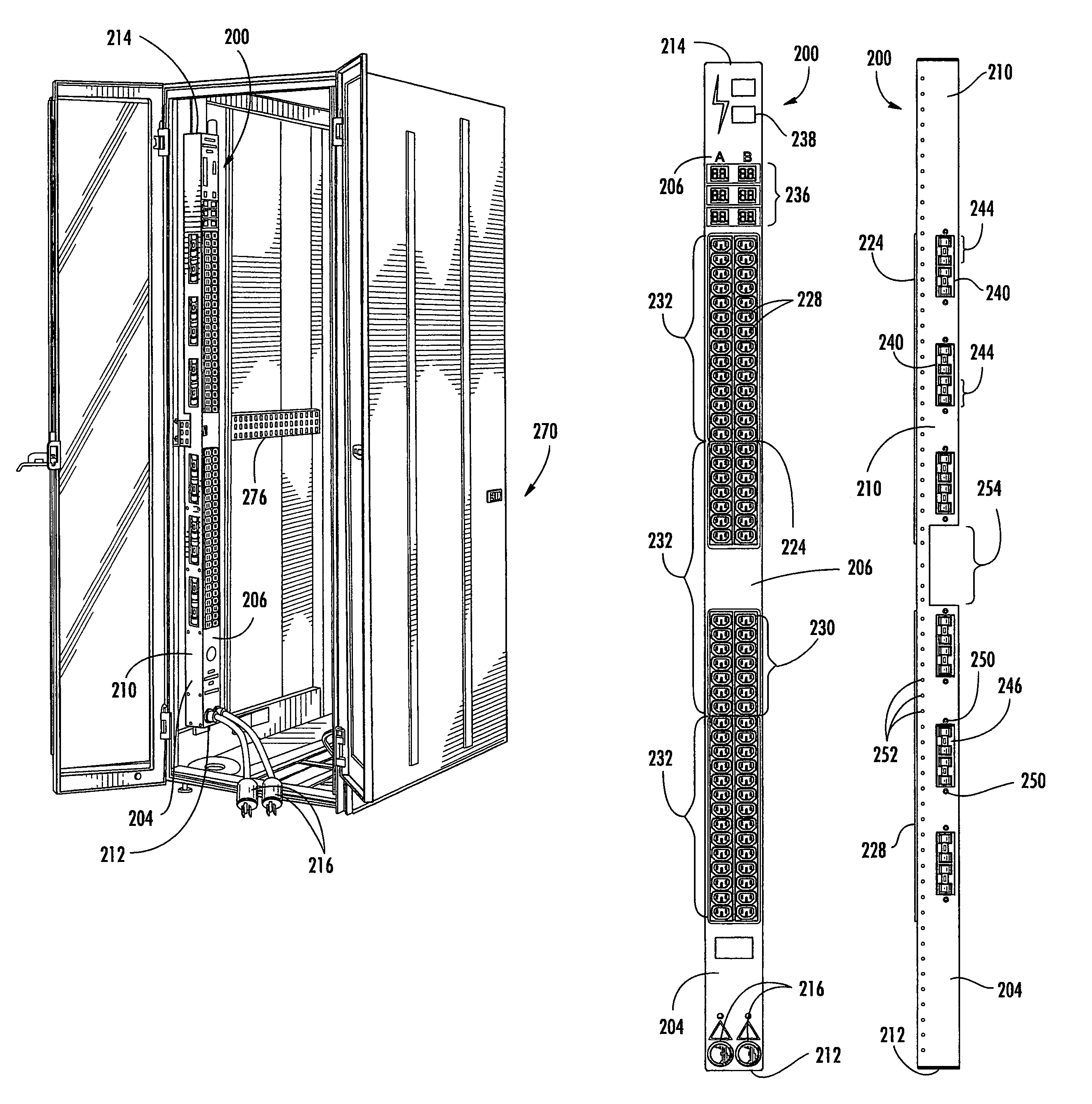
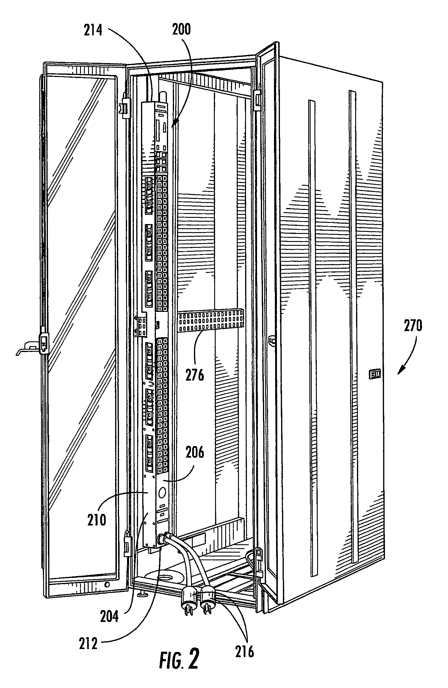
[0045]The outside of a power distribution apparatus (PDA) 200 according to an embodiment of the present invention is shown in FIG. 2. The PDA 200 has a housing 204 of any suitable dimensions. The housing 204 is preferably sized for mounting in or adjacent a rack, such as, for example, the vertical RETMA electronic equipment rack 270 shown in FIG. 2. The housing 204 is shown as a rectangular box, having longitudinally extending front 206 and back faces 208 (see FIG. 7), two longitudinally extending lateral sides 210 (one of which is shown in FIG. 2), a first end 212, and a second end 214. Of course, shapes other than rectangular boxes could be used.

[0046]The housing 204 may be made of a substantially rigid and durable material, such as metals or plastics, including polycarbonate resins. In at least one embodiment, the housing 204 is made of sheet metal, such as sheet steel or other suitable shielding material.

[0047]One or more power inputs 216 may be coupled to the housing 204. In th...


PUM


Abstract

A power distribution unit is provided that may be used to distribute power to a plurality of electronic devices. The power distribution unit may have one or more outlet gangs with integral components providing a plurality of individual power outlets. Each outlet gang may be associated with one or more power rails which deliver power to each power outlet. A connector may be located on each power rail. The power distribution unit may include a connector board for connection to two or more electronic components, such as outlet gangs. Fuse access windows may be provided to provide access to a fuse holder. The power distribution unit may have a housing having a mounting channel formed therein, which may allow the power distribution unit to be mounted in relatively to a rack having a protrusion which may be received by the mounting channel.

Description

CROSS REFERENCE TO RELATED APPLICATION[0001]This application claims priority through, and incorporates by reference, the applicants' provisional patent application, Ser. No. 60 / 624,286, filed Nov. 1, 2004, entitled Power Distribution Apparatus.BACKGROUND OF THE INVENTION[0002]1. Field of the Invention[0003]The present invention relates to power distribution apparatus. More particularly, the present invention relates to power distribution apparatus having ganged power outlets.[0004]2. Description of the Related Art[0005]Electronic equipment racks commonly consist of rectangular or box-shaped housings or rack structures. Electronic equipment is commonly mountable in such racks so that the various electronic components are aligned vertically one on top of the other in the rack. Often, multiple racks are oriented side-by-side, with each rack containing numerous electronic components and having substantial quantities of associated component wiring located both within and outside of the a...

Claims


Application Information

Patent Timeline
Patent Type & Authority Patents(United States)
IPC IPC(8): H02B1/26H01R13/46
CPCH05K7/1492
Inventor EWING, CARREL W.CLEVELAND, ANDREW J.MASKALY, JAMES P.MCGLUMPHY, DENNIS W.MOLL, NATHAN
Owner SERVER TECHNOLOGY
Why Eureka
Try Eureka