Intervertebral spacer device utilizing a spirally slotted belleville washer having radially extending grooves

a technology of intervertebral spacer and belleville washer, which is applied in the direction of spinal implants, joint implants, prostheses, etc., can solve the problems of collateral injury to the patient's spine, limiting the overall flexibility of the spinal column, and limiting the normal motion of the patien

Inactive Publication Date: 2007-09-18
HOWMEDICA OSTEONICS CORP
View PDF98 Cites 24 Cited by
  • Summary
  • Abstract
  • Description
  • Claims
  • Application Information

AI Technical Summary

Benefits of technology

[0021]This assembly provides ample spring-like performance with respect to axial compressive loads, as well as long cycle life to mimic the axial biomechanical performance of the normal human intervertebral disc. The spiral slots and radially extending grooves of the belleville washer allow the washer to expand radially as the slots and grooves widen under the load, only to spring back into its undeflected shape upon the unloading of the spring. As the washer compresses and decompresses, the annular retaining wall maintains the wide end of the washer within a prescribed boundary on the internal face of the base plate which it contacts, and an annular retaining ring maintains the wide end of the washer against the internal face.

Problems solved by technology

It is, however, important to note that the fusion of the adjacent bones is an incomplete solution to the underlying pathology as it does not cure the ailment, but rather simply masks the pathology under a stabilizing bridge of bone.
This bone fusion limits the overall flexibility of the spinal column and artificially constrains the normal motion of the patient.
This constraint can cause collateral injury to the patient's spine as additional stresses of motion, normally borne by the now-fused joint, are transferred onto the nearby facet joints and intervertebral discs.

Method used


Image

  • Intervertebral spacer device utilizing a spirally slotted belleville washer having radially extending grooves
  • Intervertebral spacer device utilizing a spirally slotted belleville washer having radially extending grooves
  • Intervertebral spacer device utilizing a spirally slotted belleville washer having radially extending grooves

Examples


Embodiment Construction

[0030]While the present invention will be described more fully hereinafter with reference to the accompanying drawings, in which particular embodiments and methods of implantation are shown, it is to be understood at the outset that persons skilled in the art may modify the invention herein described while achieving the functions and results of this invention. Accordingly, the descriptions which follow are to be understood as illustrative and exemplary of specific structures, aspects and features within the broad scope of the present invention and not as limiting of such broad scope. Like numbers refer to similar features of like elements throughout.

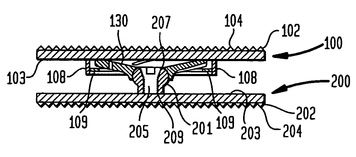
[0031]Referring now to FIGS. 3a and 3b, side cross-section views of upper and lower plate members 100,200 of the preferred embodiment of the present invention are shown. As the device is designed to be positioned between the facing surfaces of adjacent vertebral bodies, the plates include substantially flat external face portions 102,202...


PUM

PropertyMeasurementUnit
restoring forceaaaaaaaaaa
depthaaaaaaaaaa
lengthaaaaaaaaaa

Abstract

An intervertebral spacer device having a pair of opposing plates for seating against opposing vertebral bone surfaces, separated by at least one spring mechanism. The preferred spring mechanism is at least one spirally slotted belleville washer having radially extending grooves. In a preferred embodiment there is a single such belleville which is modified to mount onto a ball-shaped head. The lower plate of this embodiment includes a post extending upwardly from the inner surface of the plate, the post including a ball-shaped head. The modified Belleville washer can be rotatably mounted to the head such that the wider portion of the washer seats against the upper plate. The belleville washer has at least one radially extending groove and at least one spiral slot.

Description

CROSS-REFERENCE TO RELATED APPLICATION[0001]This application is a continuing application of U.S. patent application Ser. No. 09 / 970,479, filed Oct. 4, 2001 and entitled “Intervertebral Spacer Device Utilizing a Spirally Slotted Belleville Washer Having Radially Extending Grooves”, now U.S. Pat. No. 6,669,730, which is a continuation-in-part of U.S. patent application Ser. No. 09 / 968,046 filed Oct. 1, 2001 and entitled “Intervertebral Spacer Device Utilizing a Belleville Washer Having Radially Extending Grooves”, abandoned, which is a continuation-in-part of U.S. patent application Ser. No. 09 / 789,936, filed Feb. 15, 2001, abandoned.FIELD OF THE INVENTION[0002]This invention relates generally to a spinal implant assembly for implantation into the intervertebral space between adjacent vertebral bones to simultaneously provide stabilization and continued flexibility and proper anatomical motion, and more specifically to such a device which utilizes a spirally slotted belleville washer,...

Claims


Application Information

Patent Timeline
Patent Type & Authority Patents(United States)
IPC IPC(8): A61F2/44A61F2/00A61F2/02A61F2/30
CPCA61F2/4425A61F2/30742A61F2/30767A61F2/442A61F2002/30171A61F2002/302A61F2002/3038A61F2002/30433A61F2002/30443A61F2002/30444A61F2002/30446A61F2002/30451A61F2002/30492A61F2002/30502A61F2002/30507A61F2002/30518A61F2002/30538A61F2002/30563A61F2002/30565A61F2002/30571A61F2002/30594A61F2002/30604A61F2002/30649A61F2002/30769A61F2002/30774A61F2002/30909A61F2002/3092A61F2002/30975A61F2002/443A61F2220/0025A61F2220/0033A61F2220/0041A61F2220/0058A61F2230/005A61F2230/0065A61F2250/0006A61F2310/00017A61F2310/00023A61F2310/00365A61F2002/30331A61F2002/305
Inventor RALPH, JAMES D.TATAR, STEPHEN
Owner HOWMEDICA OSTEONICS CORP
Why Eureka
Try Eureka