Inclined optical compensation film, method for producing the same and liquid crystal display including the same

a technology of optical compensation and film, applied in the direction of polarising elements, thin material processing, instruments, etc., can solve the problems of difficult to change the inclination angle or retardation, film also has problems, and achieve excellent optical characteristics

Inactive Publication Date: 2007-09-18
NITTO DENKO CORP
View PDF40 Cites 8 Cited by
  • Summary
  • Abstract
  • Description
  • Claims
  • Application Information

AI Technical Summary

Benefits of technology

[0013]As a result of keen examination, the inventors of the present invention newly found that an inclined optical compensation film that was completely different from the conventional film was formed by selecting a non-liquid crystal polymer instead of a liquid crystal material as a forming material and further using a non-liquid crystal polymer such as polyimide among the above non-liquid crystal polymer, thus arriving at the present invention. As described above, the inclined optical compensation film that has an inclined non-liquid crystal polymer and satisfies the above-noted condition is useful for, for example, a TN mode liquid crystal display or the like similarly to a conventional inclined optical compensation film formed of a liquid crystal material (an inclined retardation film). Furthermore, since the inclined optical compensation film according to the present invention is formed of a non-liquid crystal polymer, its optical characteristics such as retardation also can be varied by stretching or shrinking, which will be described later, even after it is formed unlike a conventional liquid crystal material, which is to be solidified inevitably. Thus, it is possible to adjust the optical characteristics according to its intended use, for example, to provide even better optical characteristics, so that the inclined optical compensation film of the present invention can be applied to a wider range of purposes than a conventional inclined optical compensation film, leading to cost reduction. Moreover, since the use of the above-mentioned polyimide as the non-liquid crystal polymer satisfies the above-noted range of birefringence (Δn), an excellent visual angle compensation effect can be achieved, for example, a favorable contrast can be obtained over a wide viewing angle. Therefore, the optical compensation film according to the present invention can be used as a new retardation film that is useful for various image display apparatuses such as liquid crystal displays.
[0016]Unlike a conventional liquid crystal material, the non-liquid crystal polymer mentioned above can form a coating film that has its own property of allowing molecules to be aligned so as to exhibit an optically negative uniaxiality (nx>nz), (ny>nz) regardless of the alignment property of a base. Thus, the base is not necessarily limited to an alignment substrate or a substrate provided with an alignment layer. Also, simply by applying an external force to a coating film to be formed as above, the non-liquid crystal polymer constituting the coating film can be inclined and aligned. In this manner, it is possible to obtain a new inclined optical compensation film having excellent optical characteristics as described above.

Problems solved by technology

However, although there have been many reports on these inclined optical compensation films for TN mode obtained by inclining and aligning liquid crystal materials, these films also have some problems.
For example, their production processes are complicated because the selection of liquid crystal materials (the selection of liquid crystal materials that are inclined and aligned easily by utilizing the difference in surface energy at an interface with the air) and the control of the angle of inclination of the liquid crystal material (the control of the inclination angle by a surfactant) are necessary and an alignment substrate is indispensable.
Further, since there are various controllable factors, it is difficult to change the inclination angle or the retardation (see JP 12(2000)-105315 A, for example).

Method used


Image

  • Inclined optical compensation film, method for producing the same and liquid crystal display including the same
  • Inclined optical compensation film, method for producing the same and liquid crystal display including the same
  • Inclined optical compensation film, method for producing the same and liquid crystal display including the same

Examples


example 1

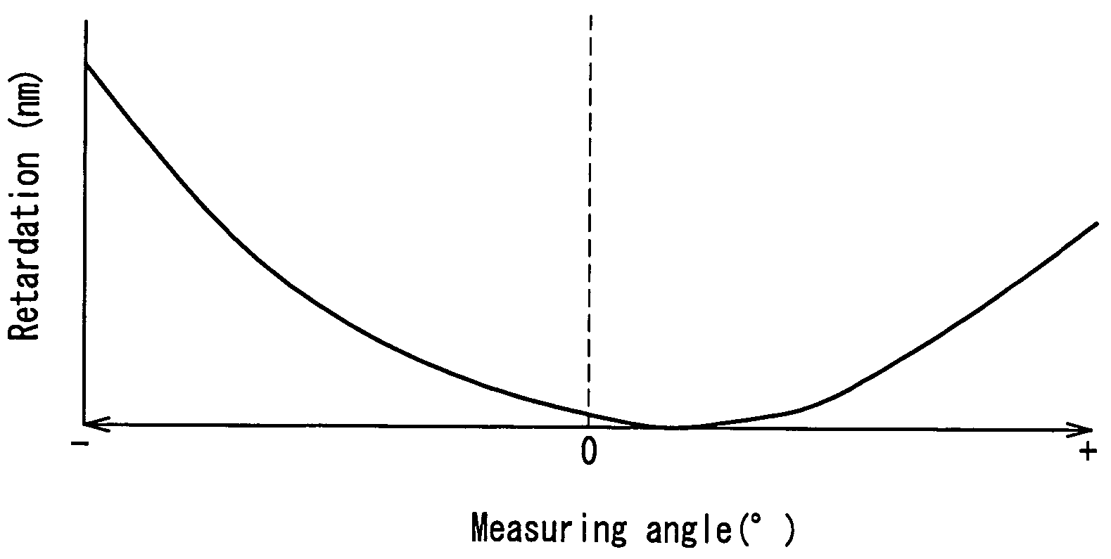
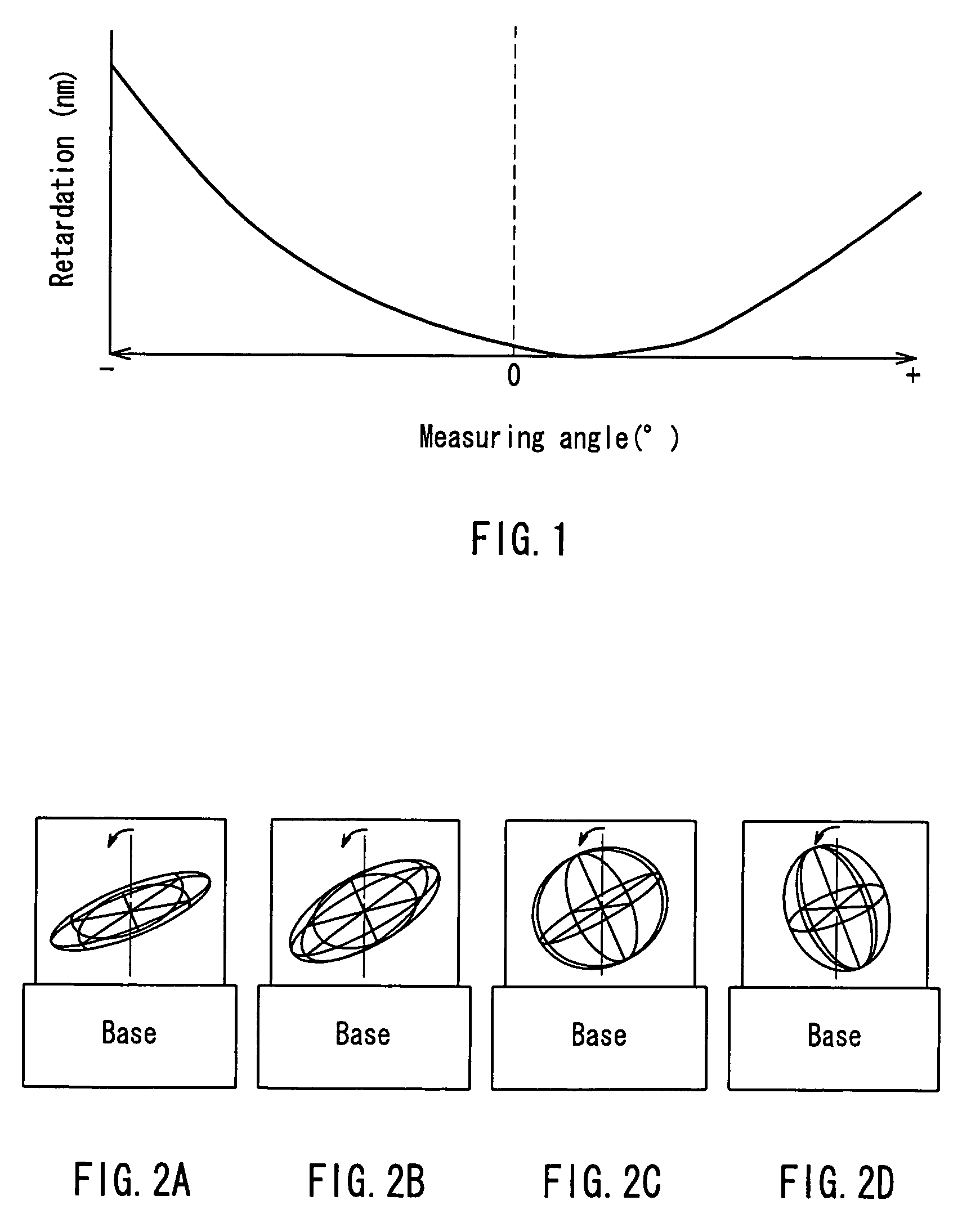
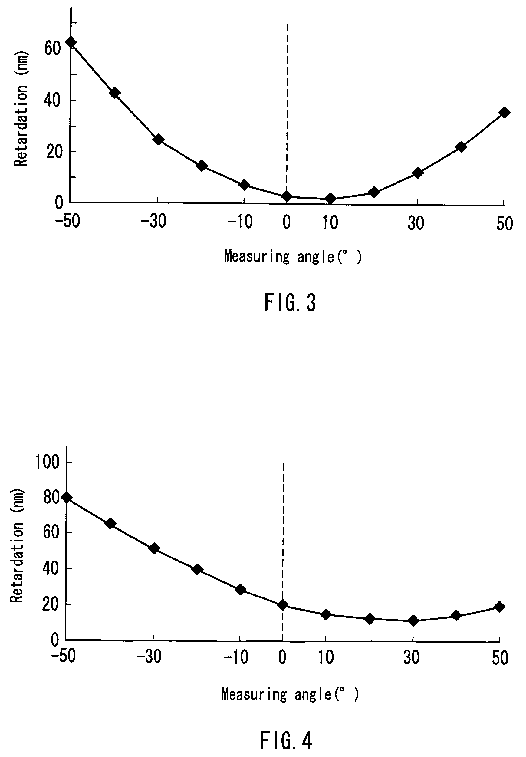
[0195]Polyimide having a weight-average molecular weight (Mw) of 70,000 synthesized from 2,2′-bis(trifluoromethyl)-4,4′,5,5′-biphenyl tetracarboxylic dianhydride and 2,2′-bis(trifluoromethyl)-4,4′-diaminobiphenyl was dissolved in cyclohexanone, thus preparing a 10 wt % polyimide solution. Then, the surface of a 75 μm thick PET film (manufactured by Toray Industries. Inc.; trade name S27) was coated with this polyimide solution. Thereafter, hot air was blown onto this coating film with a blower, thereby inclining polyimide in the coating film. The condition of this treatment was such that the air velocity was 20 m / sec, the air temperature was 100° C., the duration was 5 minutes and the distance between the surface of the coating film and the front end of the blower was 30 cm. The laminate of the PET film and the coating film was placed on a belt and sent out continuously at a speed of 2 m / minute, whereby the hot air was blown onto the laminate. Subsequently, by heating and drying at ...

control example 1

[0200]The surface of a glass plate was coated with a 1 wt % aqueous solution of polyvinyl alcohol (trade name NH-18; manufactured by The Nippon Synthetic Chemical Industry Co., Ltd.) with a spin coater, followed by drying at 120° C. for 5 minutes. In this way, a 0.5 μm thick PVA film was formed on the glass plate. Further, the surface of the PVA film was rubbed five times in one direction with a commercially available rubbing cloth, thus forming an alignment layer. The surface of this alignment layer was coated with a 10 wt % tetrachloroethylene solution of triphenylene-based discotic liquid crystal represented by the chemical formula below with a spin coater, followed by heating at 200° C. for 5 minutes, thereby aligning the liquid crystal material. By this heating treatment, a 2 μm thick inclined birefringent layer having a birefringence (Δn) of about 0.040 was formed on the alignment layer.

[0201]

[0202]Similarly to Example 1 described above, the retardation of this inclined birefr...


PUM

PropertyMeasurementUnit
thicknessaaaaaaaaaa
measuring angleaaaaaaaaaa

Abstract

An inclined optical compensation film formed from a non-liquid-crystal polymer, which is useful in a TN mode liquid crystal display. A substrate is coated with a non-liquid-crystal polymer to thereby form a coating film; the non-liquid-crystal polymer of the coating film is inclined and aligned; and the coating film is solidified, thereby forming an inclined optical compensation film. The non-liquid-crystal polymer can be inclined and aligned by, for example, applying external force, such as wind blowing, to the coating film. This inclined optical compensation film exhibits, for example, a birefringence (Δn) ranging from 0.001 to 0.5 and thus is useful in a TN mode liquid crystal display, etc.

Description

TECHNICAL FIELD[0001]The present invention relates to an inclined optical compensation film used for improving viewing angle characteristics, a method for producing the same and various image display apparatuses using the same.BACKGROUND ART[0002]Conventionally, liquid crystal displays have been provided with various retardation films for optical compensation, for example, birefringent layers formed of a polymer having a negative birefringence. As examples of the polymer having a negative birefringence, polyimide etc. are disclosed in various documents (for example, U.S. Pat. No. 5,344,916, U.S. Pat. No. 5,395,918, U.S. Pat. No. 5,480,964, U.S. Pat. No. 5,580,950, U.S. Pat. No. 5,694,187, U.S. Pat. No. 5,750,641 and U.S. Pat. No. 6,074,709). However, these negative birefringent layers can be used as an inclined optical compensation film in a liquid crystal display whose display system is a vertically aligned (VA) mode but cannot achieve a sufficient effect as an inclined optical com...

Claims


Application Information

Patent Timeline
Patent Type & Authority Patents(United States)
IPC IPC(8): G02F1/13363G02B5/30
CPCG02B5/3083G02F1/133634Y10T428/1036Y10T428/10G02F2202/022C09K2323/03C09K2323/00G02F1/13363G02F1/1335
Inventor YAMAOKA, TAKASHIMURAKAMI, NAOYOSHIMI, HIROYUKI
Owner NITTO DENKO CORP
Why Eureka
Try Eureka