Check patentability & draft patents in minutes with Patsnap Eureka AI!

Cable mount and fixture having electrical switch assembly

a technology of electrical switch and cable mount, which is applied in the direction of machine supports, wire tools, manufacturing tools, etc., can solve the problems of no prior art references, and achieve the effect of minimizing the slippage of wires and improving the friction between the cable mount and the wires

Inactive Publication Date: 2007-10-09
PANDUIT
View PDF14 Cites 3 Cited by
  • Summary
  • Abstract
  • Description
  • Claims
  • Application Information

AI Technical Summary

Benefits of technology

[0008]Preferably, the cable mount has a plurality of retention tabs to improve friction between the cable mount and the wires. The additional friction provided by the retention tabs minimizes slippage of wires across the top of the cable mount.

Problems solved by technology

However, none of the prior art references, including the '261 and '906 patents, provide an electrical switch assembly that provides electrical verification that the cable mount is correctly installed in the fixture.

Method used


Image

  • Cable mount and fixture having electrical switch assembly
  • Cable mount and fixture having electrical switch assembly
  • Cable mount and fixture having electrical switch assembly

Examples


Embodiment Construction

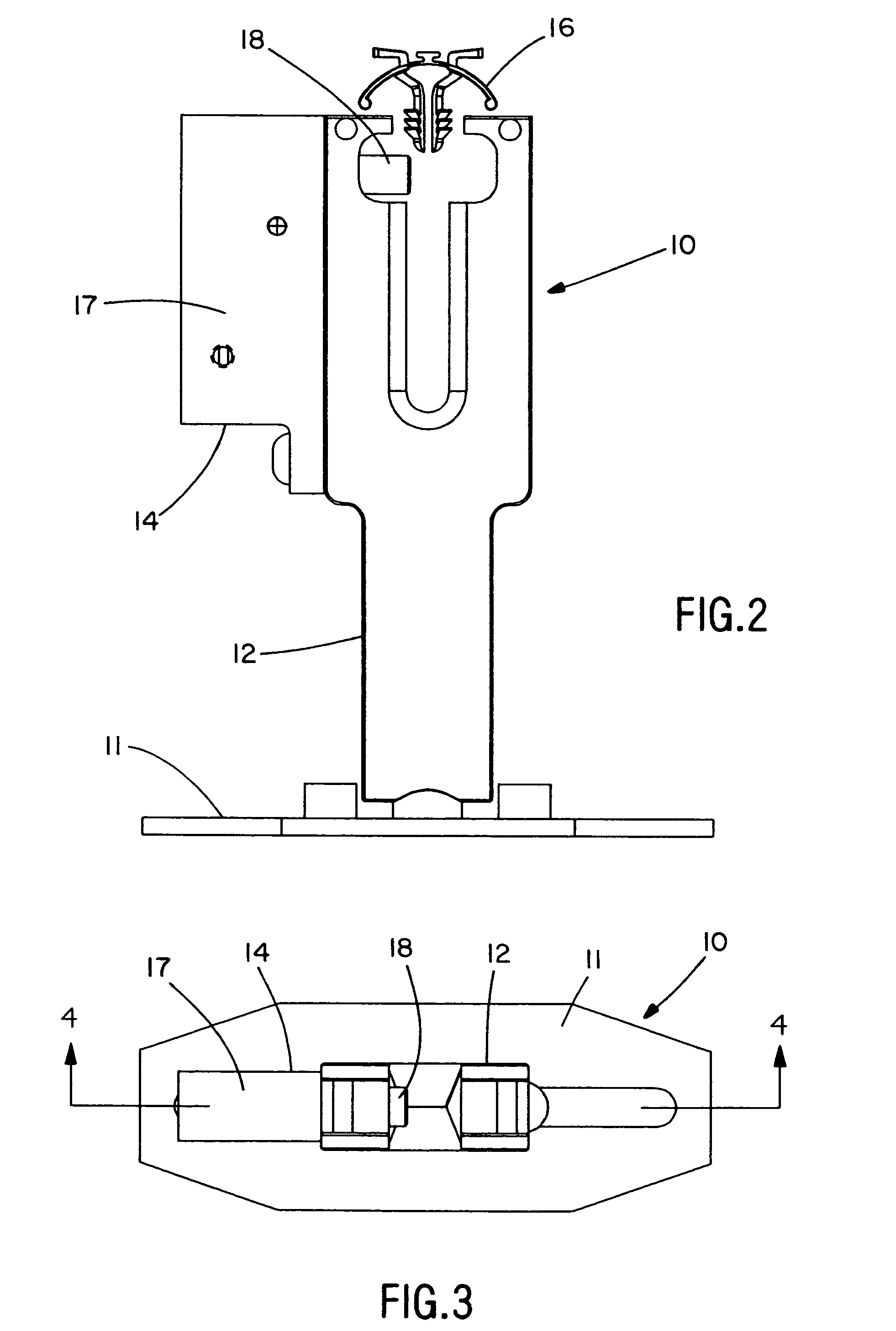
[0018]The illustrated embodiments of the invention are directed to a cable mount and fixture having an electrical switch assembly that provides electrical verification that a cable mount is correctly installed in the fixture.

[0019]FIG. 1 shows a cable mount and fixture having electrical switch assembly 10. As shown in FIGS. 1-6, assembly 10 includes base 11 mountable to a harness board (not shown) utilizing fasteners or other securement devices. Mounting fixture 12, such as the one disclosed in U.S. Pat. No. 5,799,906, mounts to base 11. Assembly 10 also includes a switch assembly 14 secured to mounting fixture 12 utilizing a fastener or other securement device. Switch assembly 14 includes an actuating signal that informs a user when cable mount 16, such as the one disclosed in U.S. Pat. No. 5,368,261, is correctly installed into mounting fixture 12. The disclosures of U.S. Pat. Nos. 5,799,906 and 5,368,261 are incorporated by reference.

[0020]As best seen in FIG. 4, switch assembly ...


PUM


Abstract

A cable mount and fixture system is disclosed. The system includes a mounting fixture, a cable mount insertable into the mounting fixture, and a switch assembly connected to the mounting fixture. The switch assembly includes an actuating signal that verifies that the cable mount is correctly installed in the mounting fixture.

Description

CROSS-REFERENCE TO RELATED APPLICATIONS[0001]This application claims priority to U.S. Provisional Application Ser. No. 60 / 499,148, filed on Aug. 29, 2003.BACKGROUND OF THE INVENTION[0002]The present invention is directed to a cable mount and fixture and, more particularly, a cable mount and fixture having an electrical switch assembly that provides electrical verification that a cable mount is correctly installed in the fixture.[0003]Cable mounts which can be secured to a bundle of wires by application of a single cable tie, preferably by an automatic tool, and a fixture for supporting the cable mount during application of the cable tie are known. For example, Panduit U.S. Pat. Nos. 5,368,261 and 5,799,906 disclose a cable mount and accompanying fixture for supporting the cable mount during application of a cable tie. However, none of the prior art references, including the '261 and '906 patents, provide an electrical switch assembly that provides electrical verification that the ca...

Claims


Application Information

Patent Timeline
Patent Type & Authority Patents(United States)
IPC IPC(8): F16L3/08F16G11/00B25B25/00F16L3/00H01H3/16H02G3/30
CPCH01H3/16
Inventor CAVENEY, JACK E.KRONZ, MARTY J.ZEMACH, GARY L.
Owner PANDUIT
Features
  • R&D
  • Intellectual Property
  • Life Sciences
  • Materials
  • Tech Scout
  • Unparalleled Data Quality
  • Higher Quality Content
  • 60% Fewer Hallucinations
Learn More