Liquid-crystal display and polarizing plate

a technology of liquid crystal display and polarizing plate, which is applied in the direction of polarizing elements, instruments, optics, etc., can solve the problem of difficult optical compensation of liquid crystal cells in all directions, and achieve the effect of simple configuration

Inactive Publication Date: 2007-12-11
FUJIFILM CORP
View PDF4 Cites 27 Cited by
  • Summary
  • Abstract
  • Description
  • Claims
  • Application Information

AI Technical Summary

Benefits of technology

[0008]It is difficult to optically compensate a liquid-crystal cell in all directions even by an optical compensatory sheet employing uniformly hybrid-aligned discotic liquid-crystal molecules. Liquid-crystal cells may be mainly observed in various directions in accordance with the intended use. For one example, a display used in a plane's cockpit may be mainly observed in a vertical (up and down) direction in the nature of the use. And for another example, a TV used in a household may be often observed by plural persons sitting beside each other and, thus, may be mainly observed in a horizontal (right and left) direction. One object of the first embodiment of the present invention is to provide a liquid-crystal display, especially TN-mode liquid-crystal display, having a simple configuration, adaptable for various applications.
[0009]Grayscale inversion tends to occur in conventional TN-mode liquid-crystal displays, even comprising a conventional optically anisotropic layer capable of improving grayscale viewing angle, in a black state when being observed in a down direction or in an oblique direction, and, thus, it is required to remove such grayscale inversion. One object of the second and the third embodiments of the present invention is to provide elliptically polarizing plate capable of improving a grayscale inversion angle without contributing to lowering grayscale viewing angle when being employed in a liquid-crystal display, especially in a TN-mode liquid-crystal display. Another object of the second embodiment or the third embodiment of the present invention is to provide a liquid-crystal display, especially a TN-mode liquid-crystal display, improved in grayscale viewing angle and grayscale inversion angle.

Problems solved by technology

It is difficult to optically compensate a liquid-crystal cell in all directions even by an optical compensatory sheet employing uniformly hybrid-aligned discotic liquid-crystal molecules.

Method used


Image

  • Liquid-crystal display and polarizing plate
  • Liquid-crystal display and polarizing plate
  • Liquid-crystal display and polarizing plate

Examples


first embodiment

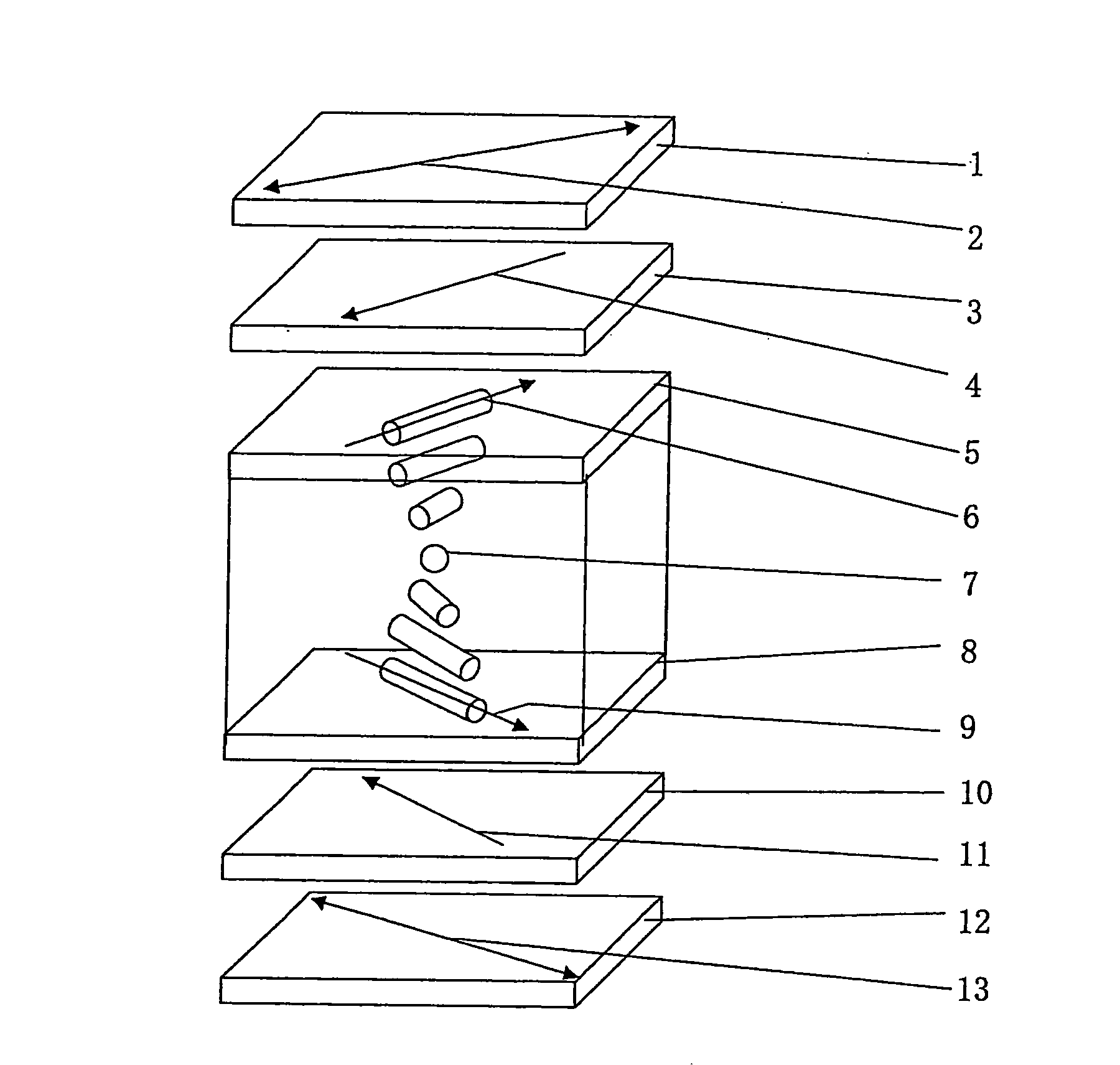
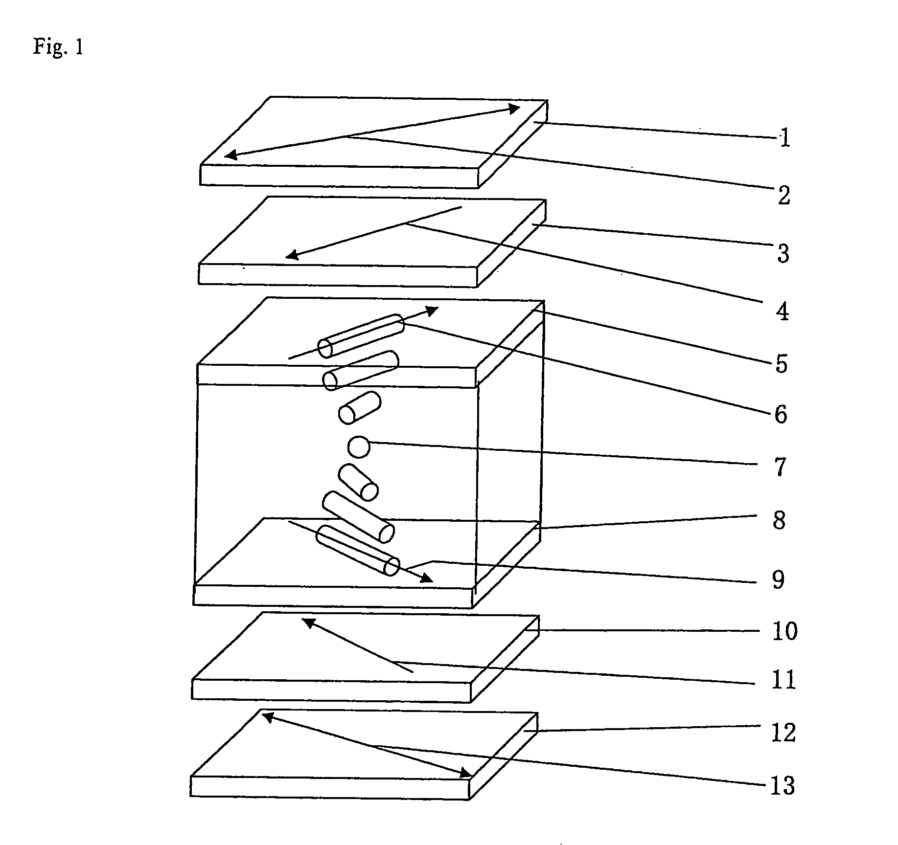
[0123]The first embodiment of the present invention relates to a liquid-crystal display comprising:

[0124]a pair of a first substrate and a second substrate disposed facing each other, and at least one of which has an electrode,

[0125]a liquid-crystal layer being sandwiched in between the pair of the first substrate and the second substrate and comprising liquid-crystal molecules aligned along with a first alignment axis and a second alignment axis respectively formed on facing surfaces of the first and second substrates,

[0126]a pair of a first polarizing plate and a second polarizing plate disposed sandwiching the liquid-crystal layer, the first polarizing plate being disposed nearer to the first substrate than the second polarizing plate and the second polarizing plate being disposed nearer to the second substrate than the first polarizing plate, and

[0127]at least a first optically anisotropic layer disposed between the liquid-crystal layer and the first polarizing plate, and compri...

second embodiment

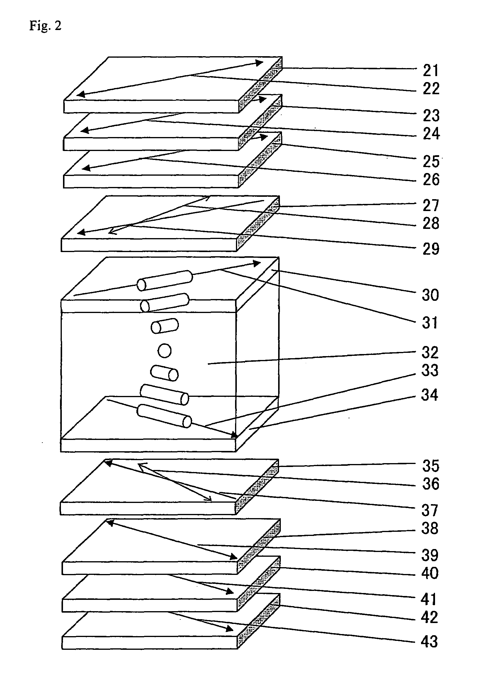
[0152]The second embodiment of the present invention relates to a liquid-crystal display comprising a pair of a first substrate and a second substrate disposed facing each other, and at least one of which has an electrode,

[0153]a liquid-crystal layer being sandwiched in between the pair of the first substrate and the second substrate and comprising liquid-crystal molecules aligned along with a first alignment axis and a second alignment axis respectively formed on facing surfaces of the first and second substrates,

[0154]a pair of a first polarizing plate and a second polarizing plate disposed sandwiching the liquid-crystal layer, the first polarizing plate being disposed nearer to the first substrate than the second polarizing plate and the second polarizing plate being disposed nearer to the second substrate than the first polarizing plate, and

[0155]at least a first optically anisotropic layer disposed between the liquid-crystal layer and the first polarizing plate, and comprising ...

third embodiment

[0181]The third embodiment of the present invention relates to a normally white mode liquid-crystal display comprising:

[0182]a pair of substrates disposed facing each other, and at least one of which has an electrode,

[0183]a liquid-crystal layer being sandwiched in between the pair of substrates and comprising liquid-crystal molecules aligned along with alignment axes respectively formed on facing surfaces of the pair of substrates, and

[0184]a pair of polarizing plates disposed sandwiching the liquid-crystal layer, comprising a linear polarizing film and at least one optically anisotropic layer having an in-plane retardation falling within a range from 30 to 80 nm;

[0185]wherein an optical quenching axis of the at least one optically anisotropic layer is not parallel to an absorption axis of the linear polarizing film,

[0186]an alignment state of the liquid-crystal molecules in the liquid-crystal layer changes depending on an applied-field thereby to vary an in-pale retardation of the...


PUM

PropertyMeasurementUnit
twist angleaaaaaaaaaa

Abstract

A novel liquid crystal display is disclosed. The display comprises a pair of substrates disposed facing each other and at least one of which has an electrode, a liquid-crystal layer being sandwiched in between the pair of substrates and comprising liquid-crystal molecules aligned along with a first alignment axis and a second alignment axis respectively formed on facing surfaces of the first and second substrates, a pair of polarizing plates disposed sandwiching the liquid-crystal layer, and at least an optically anisotropic layer disposed between the liquid-crystal layer and either of the polarizing plates, and comprising at least one liquid crystal compound which is aligned along with a third alignment axis and is fixed in the alignment state. And their disposition satisfies at least one of Condition (1): the alignment axes of the substrates are not parallel to transmission axes of the polarizing plates; and Condition (2): the alignment axis of the substrate is not parallel to the alignment axis of the optically anisotropic layer.

Description

CROSS-REFERENCE TO RELATED APPLICATIONS[0001]This application claims benefit of priority under 35 USC 119 to Japanese Patent Application No. 2004-009203 filed Jan. 16, 2004, Japanese Patent Application No. 2004-279865 filed Sep. 27, 2004, and Japanese Patent Application No. 2004-279868 filed Sep. 27, 2004.TECHNICAL FIELD[0002]The present invention relates to liquid crystal displays and polarizing plates.RELATED ART[0003]In the past, CRTs (cathode ray tube) have been mainly used for displaying equipments of office automation machines such as word processors, notebook-size personal computers or personal computers, of mobile terminals or of TVs. In recent years, liquid-crystal displays have been widely used in the place of the CRTs due to their less thickness, lighter weight and less electricity to work. A liquid-crystal display usually comprises a liquid-crystal cell and a polarizing plate. The polarizing plate usually has a protective film and a polarizer film, and is typically obtai...

Claims


Application Information

Patent Timeline
Patent Type & Authority Patents(United States)
IPC IPC(8): G02F1/1335G02F1/1337G02B5/30G02F1/13363
CPCG02B5/3016G02B5/3083G02F1/13363G02F2413/08G02F2001/133633G02F2413/02G02F2001/133531G02F1/133531G02F1/133633
Inventor TOYOOKA, KENTAROOHASHI, YUSUKEHIRAKATA, JUNICHI
Owner FUJIFILM CORP
Why Eureka
Try Eureka