Apparatus, system and method for observing combustion conditions in a gas turbine engine

a gas turbine engine and apparatus technology, applied in the direction of machines/engines, combustion types, lighting and heating apparatus, etc., can solve the problems of affecting the performance of the engine system

Active Publication Date: 2008-02-26
ROSEMOUNT AEROSPACE
View PDF15 Cites 67 Cited by
  • Summary
  • Abstract
  • Description
  • Claims
  • Application Information

AI Technical Summary

Benefits of technology

[0015]The subject invention is further directed to a system for stabilizing combustion in a gas turbine engine by observing conditions within the combustion chamber. The system includes, among other things, optical sensing means, preferably embedded within each fuel injector, for observing conditions within the combustion chamber, means for detecting combustion instabilities based upon conditions observed by the optical sensing means, and means for modulating the rate of fuel flow to the combustion chamber to reduce the detected combustion instabilities or otherwise stabilize combustion.

Problems solved by technology

Combustion instability is a significant problem in the design of low-emission, high performing combustion chambers for gas turbines, boilers, heaters and furnaces.
Combustion instability diminishes engine system performance, and the vibrations resulting from pressure oscillations can damage hardware components, including the combustion chamber.
There are many factors that contribute to combustion instability within the combustion chamber of a gas turbine.
Passive controls are often costly and limit combustor performance.
Optical sensors for observing combustion processes are known in the prior art, but they are limited in many respects.
This can cause the system to obtain inaccurate measurements.
Such a system would have limited application in a gas turbine combustor where operating temperatures are far in excess of those present in a boiler.

Method used


Image

  • Apparatus, system and method for observing combustion conditions in a gas turbine engine
  • Apparatus, system and method for observing combustion conditions in a gas turbine engine
  • Apparatus, system and method for observing combustion conditions in a gas turbine engine

Examples


Embodiment Construction

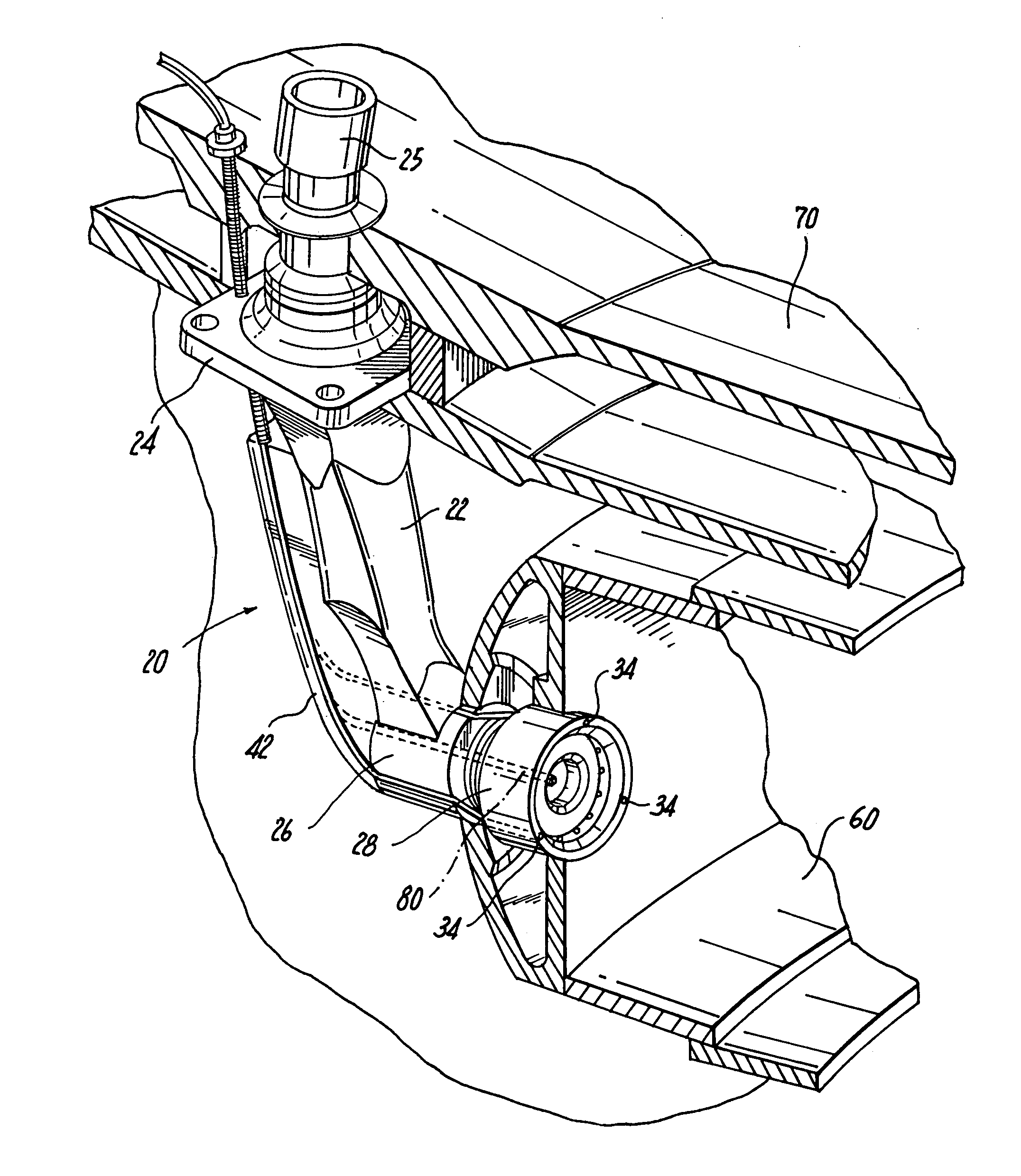
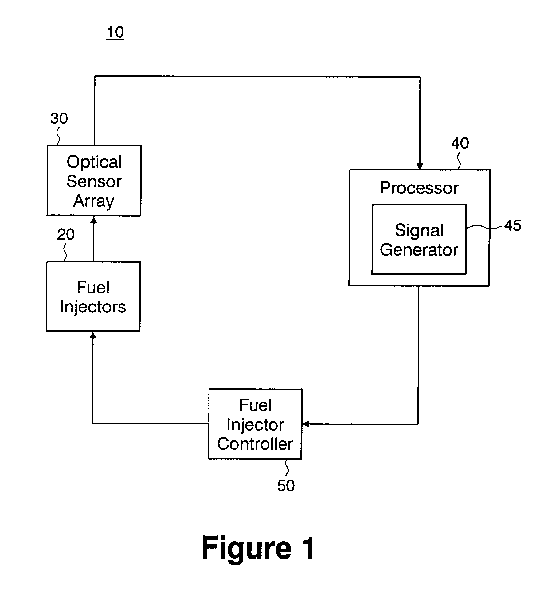
[0029]Referring now to the drawings wherein like reference numerals identify similar features or aspects of the subject invention, there is illustrated in FIG. 1 an active combustion control system configured in accordance with a preferred embodiment of the subject invention, and designated generally by reference numeral 10. The active combustion control system 10 is designed to reduce thermo-acoustic combustion instabilities within the combustion chamber of a gas turbine engine. The system is intended to lower engine emissions, improve engine dynamics and maximize operating efficiency. The active combustion control system of the subject invention is particularly well suited for use in combustion systems that are inherently unstable such as, for example, industrial gas turbine engines wherein lean premixed combustion is used to reduce NOx, and high power thrust augmented military aircraft engines (afterburners) which utilize locally rich combustion.

[0030]Referring to FIG. 1, active ...


PUM


Abstract

A fuel injector for a gas turbine combustor is disclosed which includes a feed arm having a flange for mounting the injector within the combustor and a fuel nozzle depending from the feed arm for injecting fuel into the combustor for combustion. An optical sensor array is located within the fuel nozzle for observing combustion conditions within the combustor.

Description

BACKGROUND OF THE INVENTION[0001]1. Field of the Invention[0002]The subject invention is directed to optical sensors for gas turbine engines, and more particularly, to an apparatus, system and method for observing the spectral and thermal characteristics of a flame in the combustion chamber of a gas turbine engine to detect, in real-time, conditions indicative of combustion instabilities and the like.[0003]2. Background of the Related Art[0004]Combustion instability is a significant problem in the design of low-emission, high performing combustion chambers for gas turbines, boilers, heaters and furnaces. Combustion instability is generally understood as high amplitude pressure oscillations that occur as a result of the turbulent nature of a combustion process and the large volumetric energy release within the combustion chamber. Combustion instability diminishes engine system performance, and the vibrations resulting from pressure oscillations can damage hardware components, includi...

Claims


Application Information

Patent Timeline
Patent Type & Authority Patents(United States)
IPC IPC(8): F02C7/00F01D17/02F01D21/00F02C9/26F02C9/28F23N5/08
CPCF01D17/02F01D21/003F02C9/28F23N5/082F23N2029/04F23N2029/08F23N2041/20Y02T50/677F23N2229/04F23N2229/08F23N2241/20G01N21/76Y02T50/60
Inventor MYHRE, DOUGLAS C.
Owner ROSEMOUNT AEROSPACE
Why Eureka
Try Eureka