Low power, scalable multichannel high voltage controller

a high voltage controller, low power technology, applied in the direction of dc network circuit arrangement, dc source parallel operation, ac network voltage adjustment, etc., can solve the problems of high voltage supplies typically required for each electrode, high cost and bulky, and the inability to control the flow of fluid through the complex microfluidic system. the effect of electrokinetic force movemen

Inactive Publication Date: 2008-03-25
NAT TECH & ENG SOLUTIONS OF SANDIA LLC
View PDF5 Cites 2 Cited by
  • Summary
  • Abstract
  • Description
  • Claims
  • Application Information

AI Technical Summary

Benefits of technology

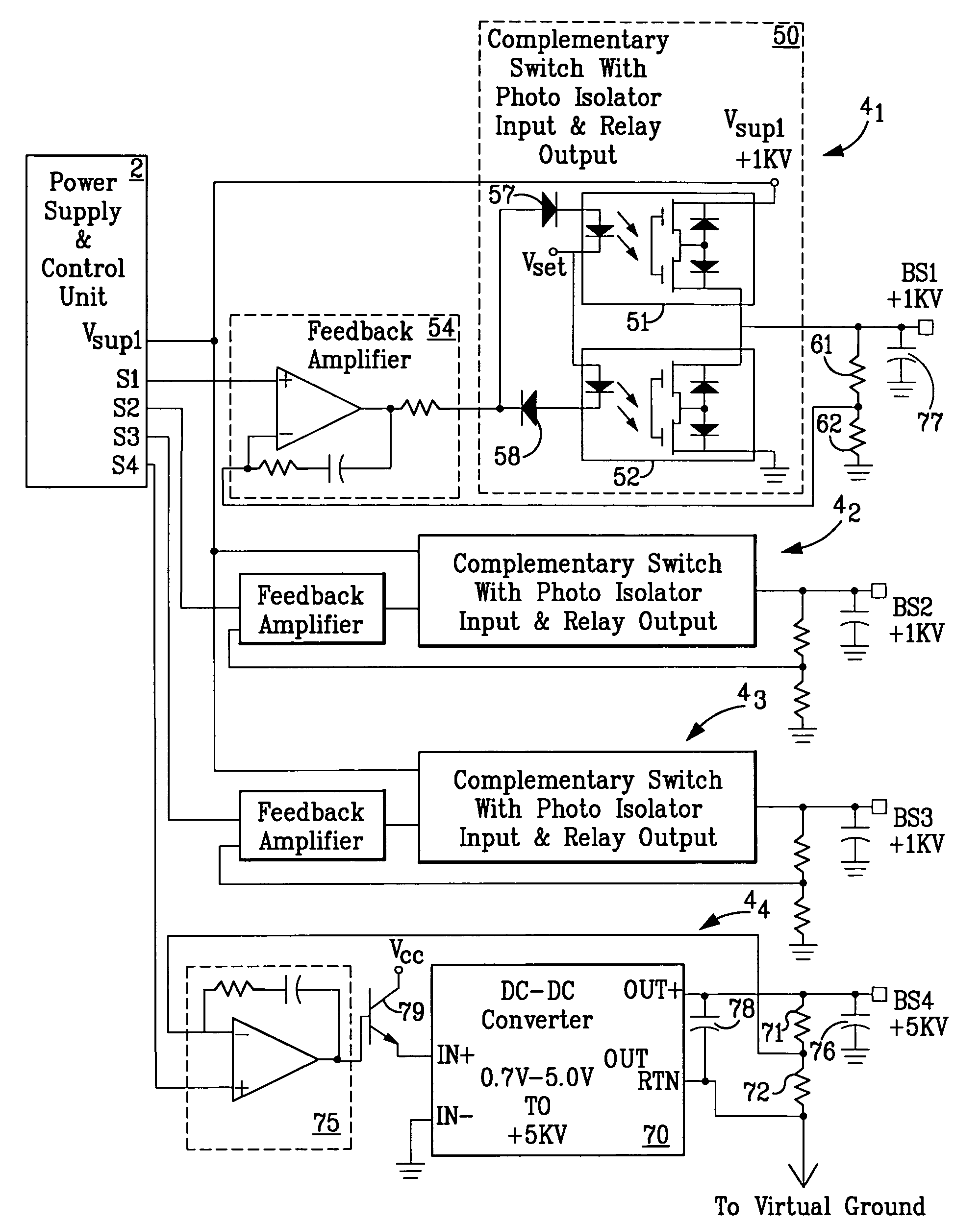
[0010]In accordance with the present invention, a power distribution system is provided which may be used to provide voltages to loads, such as electrodes in a microfluidic system. In the system, individually controlled channel switching circuits are provided to distribute power from a central high voltage supply circuit. The individual channel switching circuits, less complex than the central supply, distribute power to enable a reduction in cost and size from the use of multiple central high voltage supplies, typically making up a power distribution system.
[0011]In the system according to the present invention, voltage is distributed to each individual load (or electrode) and controlled using the channel switches connected to high voltage bus lines. The channel switches each include complementary pull up and pull down photo isolator relays with photo isolator relay switching controlled from the central high voltage supply to provide a desired bus line voltage. The ability of the photo isolator relays to switch current of varying amounts enables precise control of voltage on each bus line.
[0012]In addition to control from the central power supply, switching of the photo isolators is further controlled in each channel switch circuit using feedback from a resistor divider circuit to maintain the bus voltage swing within desired limits. The divider circuit lowers the read-out voltage of the channel node so that special high-voltage voltmeters are not required. The divider circuits are also designed to draw negligible currents from the channels, thereby minimizing unwanted electrochemical effects such as gas generation if the system is used to control a microfluidics system.
[0014]Thus, in one embodiments the system of the present invention is used to provide voltages to control a plurality of interconnected capillary channels of a microfluidic system. The voltages are applied to a plurality of electrodes at different nodes of the capillary channels to create electric fields in the capillary channels to electrokinetically move fluids. The voltages applied are set by the central high voltage control circuit and applied through signals to the individual channel switch circuits. Programmable control using the central high voltage control circuit with current measurement feedback enables precise control of fluid movement through a plurality of interconnected capillary channels.

Problems solved by technology

High voltage supplies typically required for each electrode are expensive and bulky.
Thus the cost of a complex microfluidic system using electrokinetic forces for fluid movement may be prohibitive.

Method used


Image

  • Low power, scalable multichannel high voltage controller
  • Low power, scalable multichannel high voltage controller
  • Low power, scalable multichannel high voltage controller

Examples


Embodiment Construction

[0022]FIG. 1 shows a diagram of a portion of a microfluidic system with a power distribution system according to the present invention. The power distribution system includes a power supply & control unit 2 that supplies both power and control signals to a plurality of channel switching circuits 4. The channel switch circuits 4 distribute voltage signals over power supply bus lines 6 to individual electrodes 11-15 provided in reservoirs 21-25 of a microfluidics system.

[0023]The reservoirs 21-25 are fluidly connected at the ends of channels 31-33 to form the microfluidics system. The microfluidics reservoirs and channels are formed in a planar substrate 27. The microfluidic system transports fluids from reservoirs 21-25 through the various channels 21-23 of substrate 27. To move materials through the channels 21-23, the channel switching circuits 4 apply selectable voltage levels, including ground, to each of the reservoirs 21-25. Power is supplied to the channel switching circuits 4...


PUM


Abstract

A low voltage control circuit is provided for individually controlling high voltage power provided over bus lines to a multitude of interconnected loads. An example of a load is a drive for capillary channels in a microfluidic system. Control is distributed from a central high voltage circuit, rather than using a number of large expensive central high voltage circuits to enable reducing circuit size and cost. Voltage is distributed to each individual load and controlled using a number of high voltage controller channel switches connected to high voltage bus lines. The channel switches each include complementary pull up and pull down photo isolator relays with photo isolator switching controlled from the central high voltage circuit to provide a desired bus line voltage. Switching of the photo isolator relays is further controlled in each channel switch using feedback from a resistor divider circuit to maintain the bus voltage swing within desired limits. Current sensing is provided using a switched resistive load in each channel switch, with switching of the resistive loads controlled from the central high voltage circuit.

Description

CROSS REFERENCE TO RELATED APPLICATIONS[0001]This application is a divisional application of prior U.S. patent application Ser. No. 10 / 454,179, now U.S. patent Ser. No. 7,012,342, originally filed Jun. 3, 2003 entitled “Low Power, Scalable Multichannel High Voltage Controller”, which is herein incorporated by reference in its entirety.STATEMENT OF GOVERNMENT INTEREST[0002]This invention was made with Government support under government contract DE-AC04-94AL85000 awarded by the U.S. Department of Energy to Sandia Corporation. The Government has certain rights in the invention, including a paid-up license and the right, in limited circumstances, to require the owner of any patent issuing in this invention to license others on reasonable terms.BACKGROUND[0003]1. Technical Field[0004]The present invention relates to a voltage controller system for providing stable high voltage bus line voltages using low voltage control signals while minimizing circuit cost and size. More particularly, ...

Claims


Application Information

Patent Timeline
Patent Type & AuthorityPatents(United States)
IPC IPC(8): H02J1/00
CPCH02J1/08H02M1/092H02J2001/008H02M2001/0009H02M2001/008H02J1/082H02M1/008H02M1/0009
InventorSTAMPS, JAMES FREDERICKCROCKER, ROBERT WARDYEE, DANIEL DADWADILS, DAVID WRIGHT
OwnerNAT TECH & ENG SOLUTIONS OF SANDIA LLC