Optical disk apparatus and waiting method thereof

a technology of optical disk and recording apparatus, which is applied in the direction of digital signal error detection/correction, instruments, recording signal processing, etc., can solve the problems of only reproducing the above-described conventional optical disk apparatus, not solving specific problems of optical disk recording apparatus, and extreme instability

Inactive Publication Date: 2008-04-08
KK TOSHIBA
View PDF14 Cites 6 Cited by
  • Summary
  • Abstract
  • Description
  • Claims
  • Application Information

AI Technical Summary

Benefits of technology

[0012]According to an aspect of the present invention, there is provided an optical disk apparatus comprising: an optical head which irradiates an optical disk having an information recording layer with a laser beam or receives reflected wave, and performs recording processing or reproducing processing; a waiting position decision portion which detects physical properties of eac

Problems solved by technology

However, in a recordable type of optical disk, because a recorded region differs from an unrecorded region in reflectivity of a recording layer, holding a servo state at a boundary between the recorded region and the unrecorded region is to perform the servo at a region where a servo signal level fluctuates, so that it is an extremely unstable state.
That is, the above-described conventional optical disk apparatus is reproduce-only, and can not solve specific problems of the optical disk recording apparatus.
As a result, it is difficult to perform the precise servo in the boundary region between the recorded region and the unrecorded region, like the conventional optical disk apparatus, possibility arises that the optical disk apparatus is positioned at both regions of

Method used


Image

  • Optical disk apparatus and waiting method thereof
  • Optical disk apparatus and waiting method thereof
  • Optical disk apparatus and waiting method thereof

Examples


first embodiment

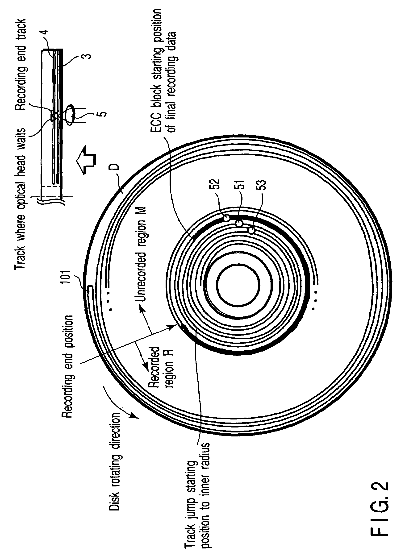
[0039]In the optical disk apparatus for the optical disk having one or more recording layers, the first embodiment is to provide the optical disk apparatus causing an optical head to wait at a position before an unrecorded region by a predetermined amount after the recording or reproducing processing is completed. FIGS. 5 to 9 are views showing each example of a waiting position of the optical head in the optical disk, and FIGS. 10, 11 and 17 are flow charts for explaining waiting processing of the optical head including a layer jump of the optical disk apparatus, and the waiting method thereof.

(Principle of the Waiting Method of the Optical Head of the Invention)

[0040]The reflectivity of a recorded region R is largely different from that of an unrecorded region M and the servo becomes easily unstable in the optical head waits near the boundary between the recorded region R and the unrecorded region M in the recordable optical disk having the information recording layer. Therefore, ...

second embodiment

[0100]In the optical disk apparatus specified in the first embodiment of the invention, a second embodiment is to provide the optical disk apparatus and the waiting method thereof, in which the waiting position of the optical head with respect to the unrecorded region or the recordable region is set on the inner radius side of the unrecorded region or the recordable region when the optical disk has a track structure in which the recording is performed from the inner radius side to the outer radius side, and the waiting position is set on the outer radius side of the unrecorded region or the recordable region when the optical disk has a truck structure in which the recording is performed from the outer radius side to the inner radius side. FIG. 12 shows an example of the waiting position of the optical head in the optical disk apparatus according to the second embodiment of the invention.

[0101]The optical disk D shown in FIG. 12 has two information recording layers on one side, the t...

third embodiment

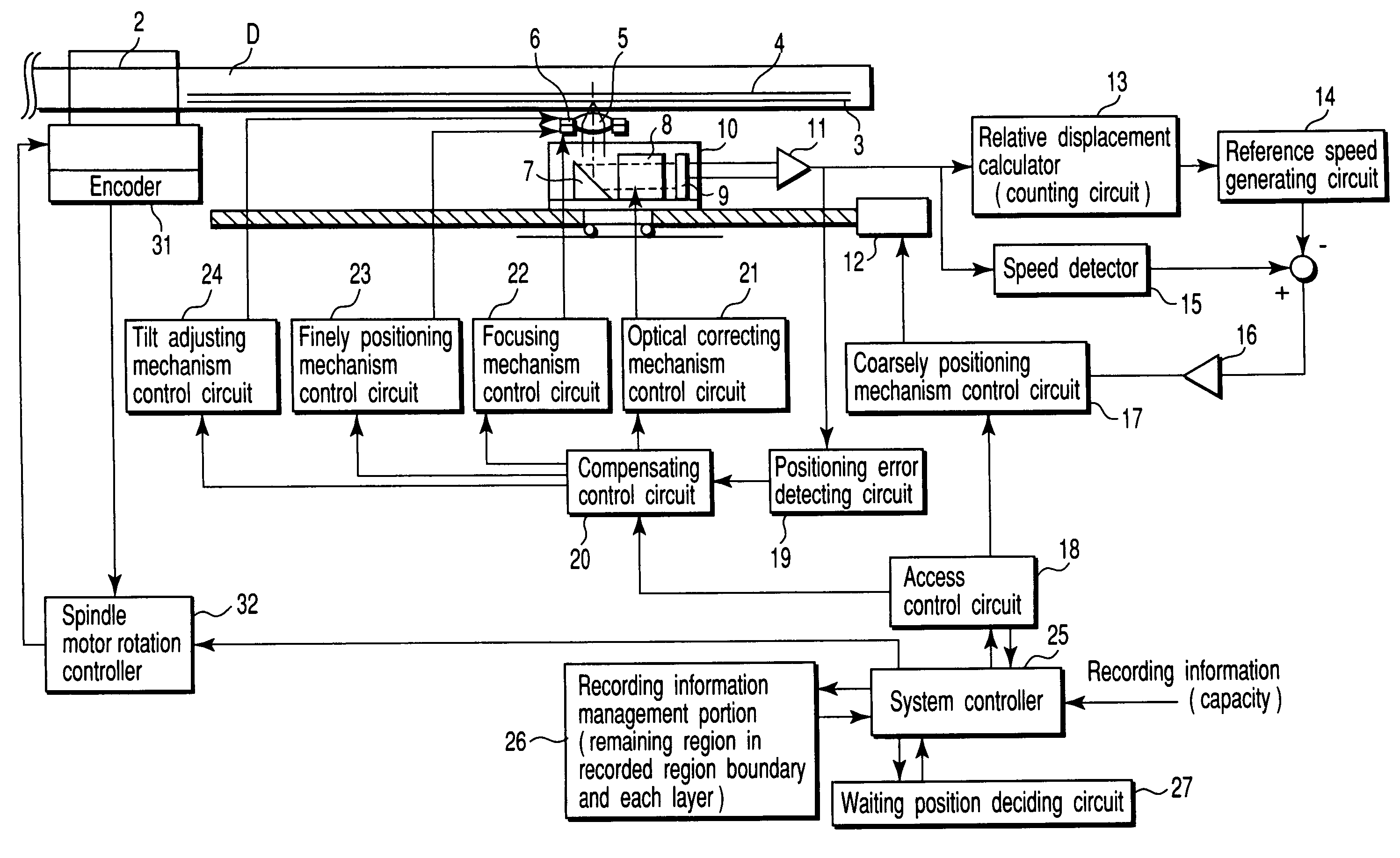
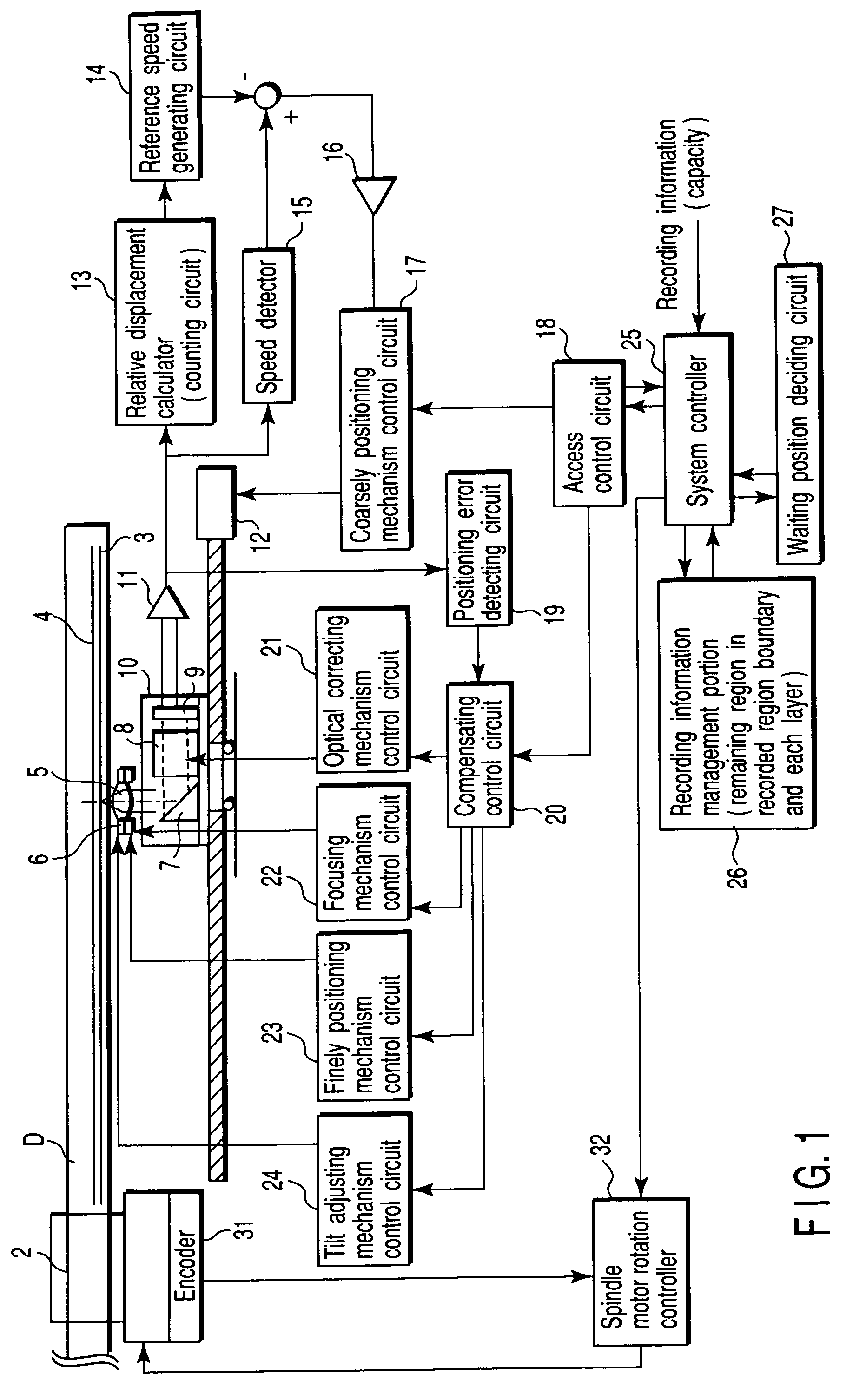
[0107]In the optical disk apparatus specified in the first embodiment of the invention, a third embodiment is to provide the optical disk apparatus and the waiting method thereof, in which a region that should have the priority for the waiting position when the plural unrecorded regions exist is specified in the case of a track structure having the recorded region in a groove and a land. FIG. 13 shows an example showing the waiting position of the optical head in the optical disk apparatus according to the third embodiment of the invention, FIGS. 14 and 15 are flow charts for explaining an example of the waiting method according to the third embodiment, and FIG. 16 is a block diagram showing an example of the optical disk apparatus according to the third embodiment.

[0108]The optical disk D for the third embodiment is shown in FIG. 12, and the optical disk has a truck structure having the recorded region in both the groove and the land. Further, as shown in FIG. 16, the optical disk ...


PUM


Abstract

An optical disk apparatus including a waiting position determining circuit which detects physical properties of each region in an optical disk after recording or reproducing processing is finished and decides a waiting position of an optical head according to the detection, and various kinds of control mechanisms which controls a position of the optical head according to the decided waiting position in order to move the optical head, is provided. By making the optical head wait at a position before two or more tracks in an unrecorded region, the recording processing can be resumed stably and surely and the recording processing can be preferentially performed in the remaining unrecorded region.

Description

CROSS-REFERENCE TO RELATED APPLICATIONS[0001]This application is based upon and claims the benefit of priority from the prior Japanese Patent Application No. 2002-190892, filed Jun. 28, 2002, the entire contents of which are incorporated herein by reference.BACKGROUND OF THE INVENTION[0002]1. Field of the Invention[0003]The present invention relates to an optical disk apparatus causing an optical head to wait before an unrecorded region after recording and reproducing processing of an optical disk, and a waiting method thereof.[0004]2. Description of the Related Art[0005]Recently, an optical disk apparatus such as DVD (Digital Versatile Disc) has been developed and comes widespread. Further added value such as operating reliability and usability is required for the optical disk drive. For example, in an optical disk apparatus described in Jpn. Pat. Appln. KOKAI Publication No. 10-79126, the optical disk apparatus decides whether an optical disk is OTP or PTP in reproducing the optic...

Claims


Application Information

Patent Timeline
IPC IPC(8): G11B7/00G11B7/007G11B7/085G11B7/09
CPCG11B7/08505G11B7/08511G11B7/00718G11B2007/0013
Inventor YONEZAWA, MINORU
Owner KK TOSHIBA
Why Eureka
Try Eureka