
Fire sprinkler flexible piping system, bracing apparatus therefor, and method of installing a fire sprinkler
a flexible piping and fire sprinkler technology, applied in the field of fire sprinkler systems, can solve the problems of slow installation, leakage of distribution system, and inability to test pressure,
- Summary
- Abstract
- Description
- Claims
- Application Information
AI Technical Summary
Benefits of technology
Problems solved by technology
Method used
Image

Examples
Embodiment Construction
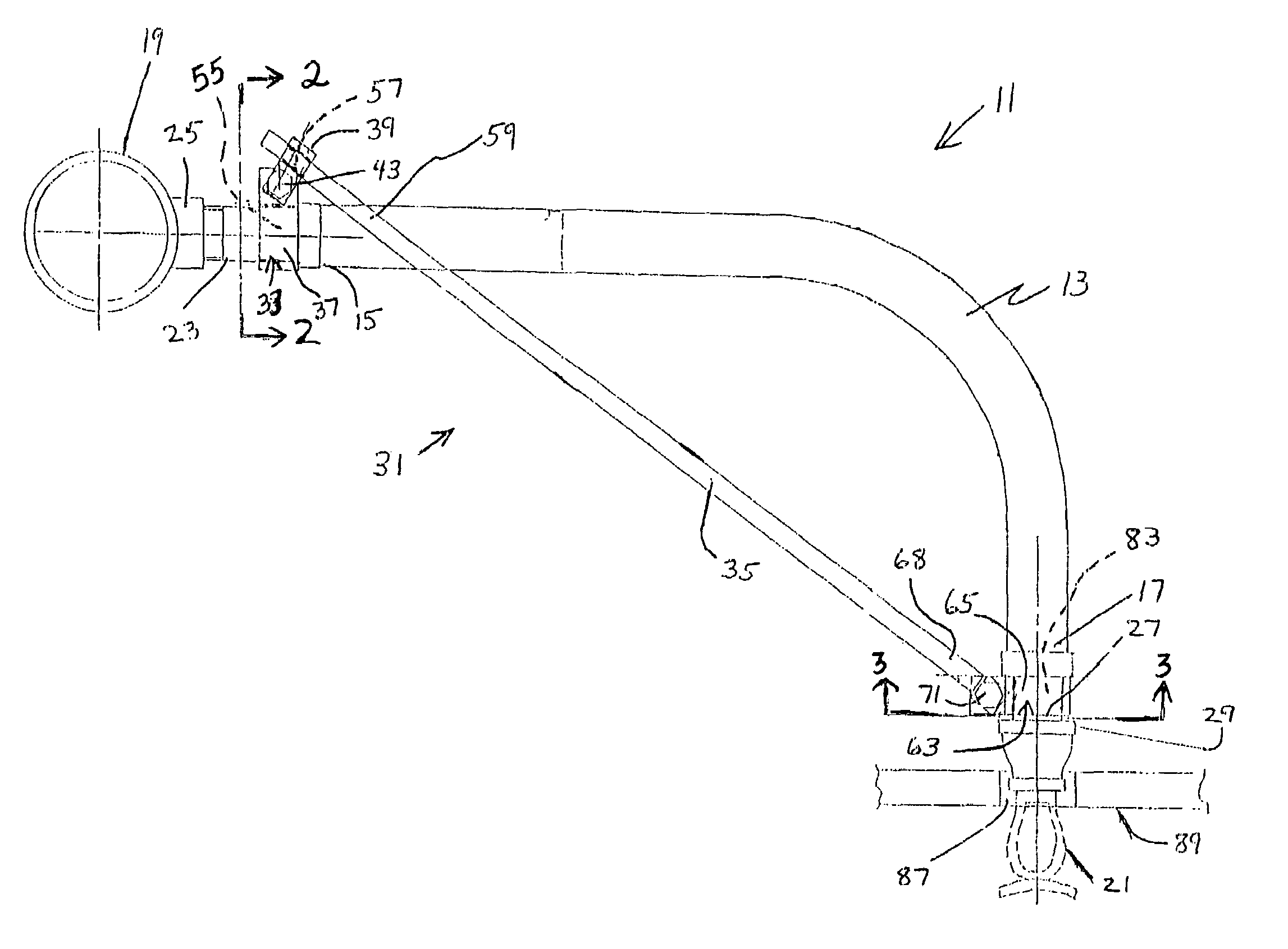
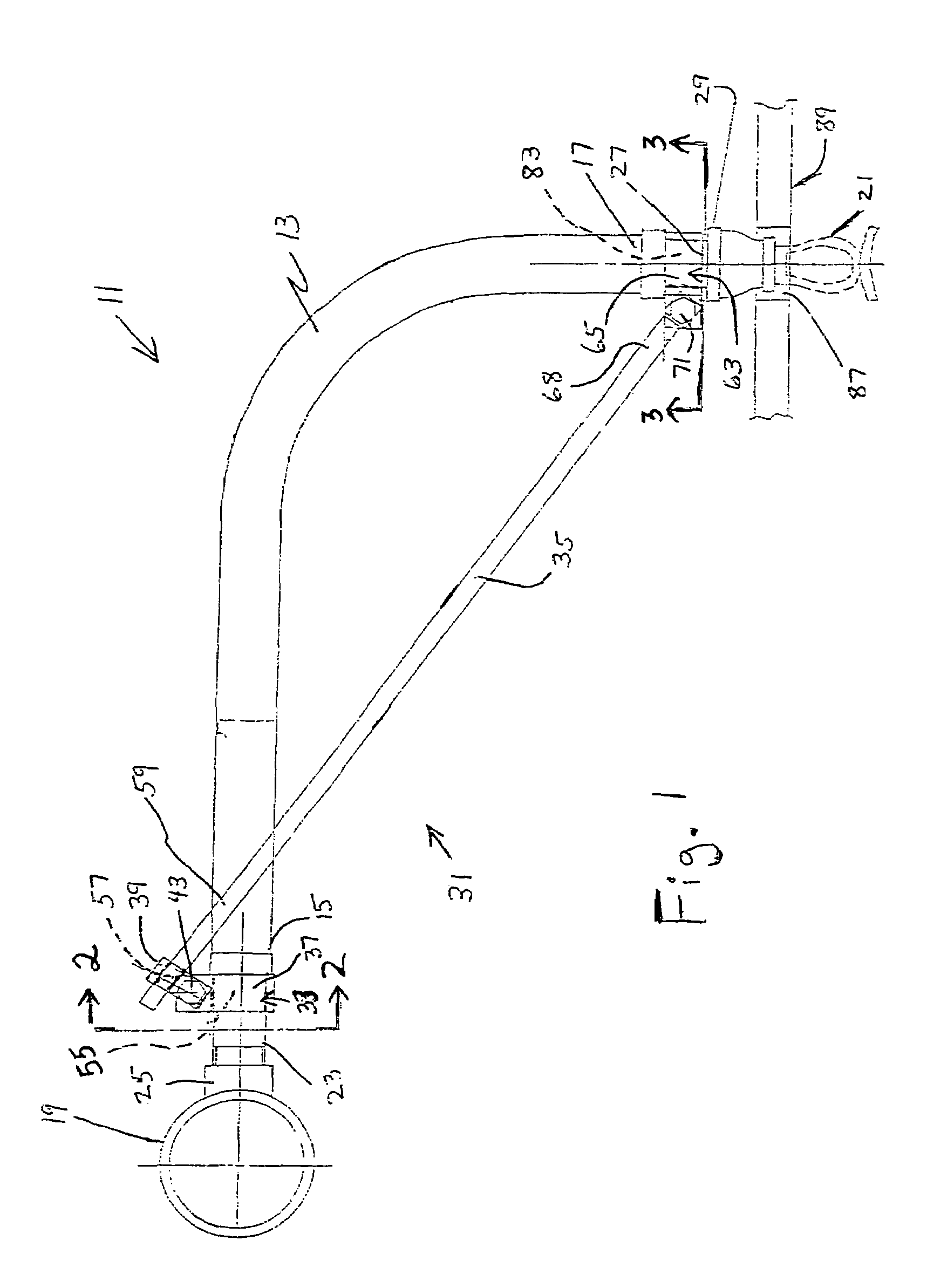
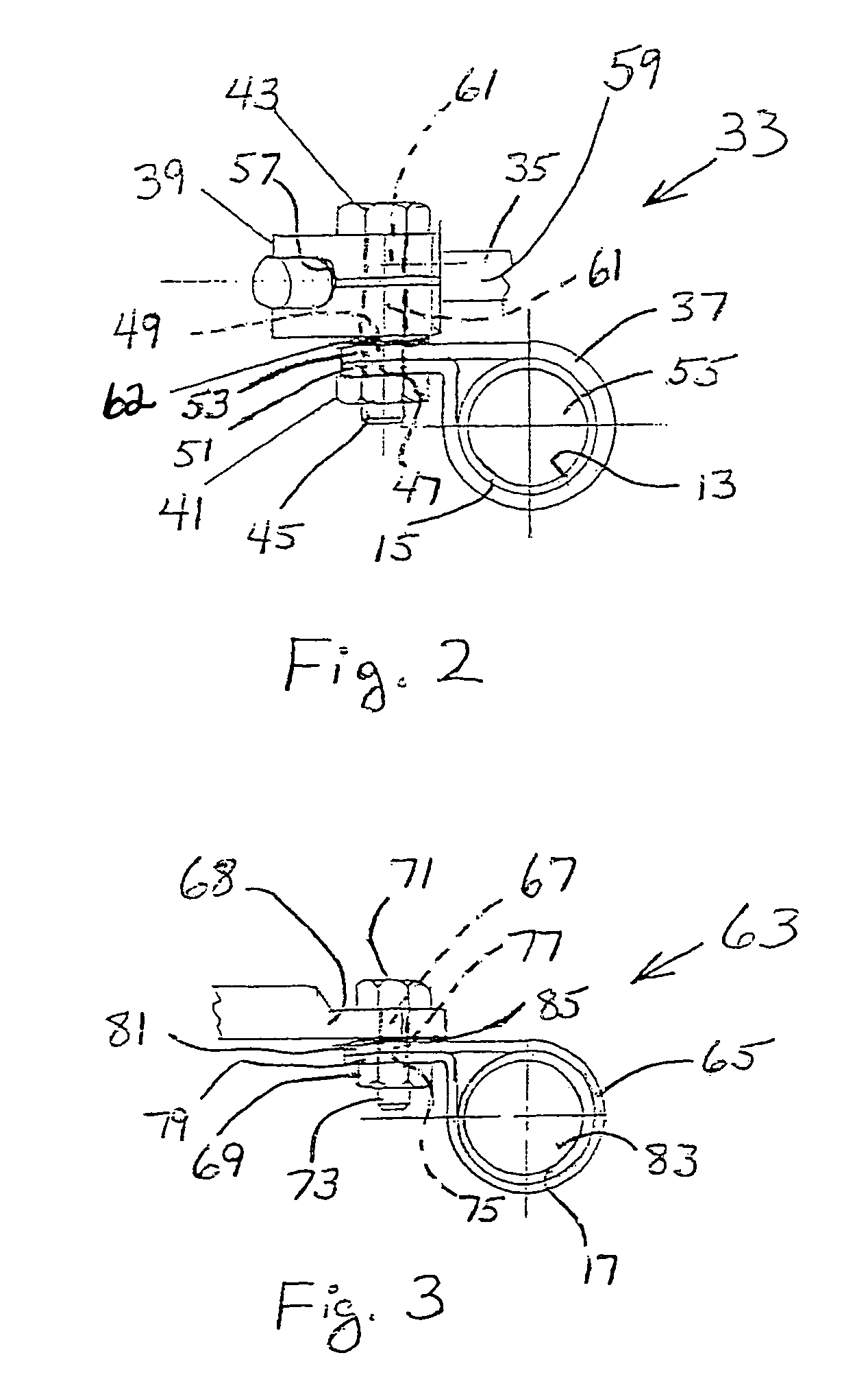
[0013]Turning now to the drawings, that are shown in FIGS. 1, 2, and 3 a flexible piping system 11 for a ceiling tile fire sprinkler installation constructed in accordance with the invention. A flexible pipe 13 is provided having a first end portion 15 and a second end portion 17, and the flexible pipe 13 is used for conveying a fire suppressing fluid, typically water, from a fire sprinkler header pipe (e.g., branch line or cross main) 19 to a sprinkler 21. As shown, the first end portion 15 of the flexible pipe 13 attaches to the header pipe 19, and the second end portion 17 of the flexible pipe 13 attaches to the sprinkler 21. Preferably, the first end portion 15 of the flexible pipe 13 has a male pipe threaded nipple 23 which engages a female threaded fitting 25 on the header pipe 19, and the second end portion 17 of the flexible pipe 13 has a male pipe threaded nipple 27 which engages a reducing coupling 29 to which the sprinkler 21 attaches. The use of the reducing coupling 29 ...
PUM
| Property | Measurement | Unit |
|---|---|---|
| pressures | aaaaa | aaaaa |
| flexible | aaaaa | aaaaa |
| length | aaaaa | aaaaa |
Abstract
Description
Claims
Application Information