Directional support structure

a support structure and directional technology, applied in the direction of branching pipes, solar thermal energy generation, shores, etc., can solve the problems of inability to both precisely hold large directional objects while allowing for ease of adjustment, lack of support structures in the art, and inability to meet the needs of large directional objects, etc., to achieve precise adjustment, prevent further rotational movement, and eliminate disengagement of directional devices

Inactive Publication Date: 2008-05-20
STANEY WAYNE
View PDF31 Cites 56 Cited by
  • Summary
  • Abstract
  • Description
  • Claims
  • Application Information

AI Technical Summary

Benefits of technology

[0006]Set forth is a directional support structure for use with solar panels, flat or raised satellite antennas, and the like structures required to be directionally facing a fixed point in space. The directional support structure includes an adjustable bracket that allows for pivoting of the mounting plate even when the mounting plate is loaded with solar panels or satellite panels, despite the weight of such devices. Rotational or azimuth movement is maintained by use of a mounting bracket secured to a base member that allows rotation with operator safety in mind by eliminating disengagement of the directional devices once they are secured to the mounting plate. Upon proper rotational placement, flanges are fastened together sandwiching a flaring located on the lower end of the mounting bracket thereby preventing further rotational movement. An adjustment bracket is provided to allow latitude adjustment of the mounting plate by use of turn buckles that provide precise adjustment and absolute rigidity upon locking of the turn buckles. A base member includes a hollow column that can be placed in the ground or bolted on a fixed structure. The column is hollow to provide a wire chase for concealment of pipes and / or electrical wiring.
[0008]Yet another objective of the invention is to provide a support structure that provides a safe structure for installers by creating a rigid mounting base that allows for positional adjustment.

Problems solved by technology

The weight of the panels is dependant upon the panel size but can be quite heavy if the solar panel includes circulating water.
One of the problems with the prior art support structures is their inability to both precisely hold large directional objects while allowing for ease of adjustment.
This need arises as conventional support structures place a burden upon the installer to prevent damage during directional positioning.
Prior art devices have not disclosed the necessity for a support structure capable of withstanding extremely high winds from causes such as hurricanes.
Such high winds can cause misadjustment if the panel moves even one inch.
Thus, what is lacking in the art is a heavy duty directional support structure capable of holding large heavy panels yet provide ease in directionally pointing by allowing the installer to rotate and tilt the directional panel as necessary.

Method used


Image

  • Directional support structure
  • Directional support structure
  • Directional support structure

Examples


Embodiment Construction

[0023]Detailed embodiments of the present invention are disclosed herein; however, it is to be understood that the disclosed embodiments are merely exemplary of the invention which may be embodied in various forms. Therefore, specific structural and functional details disclosed herein are not to be interpreted as limiting, but merely as a basis for the claims and as a representative basis for teaching one skilled in the art to variously employ the present invention in virtually any appropriate structure.

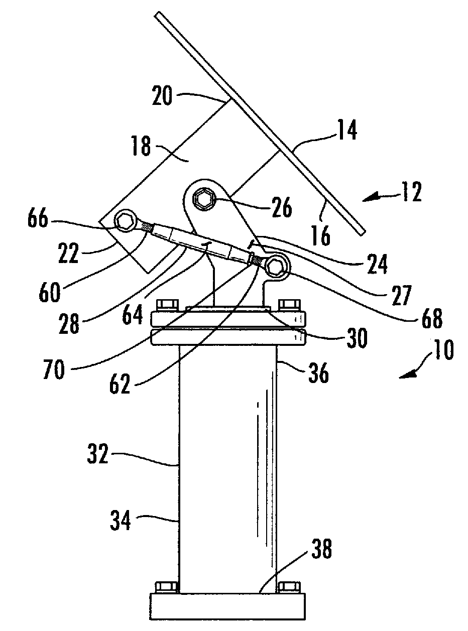
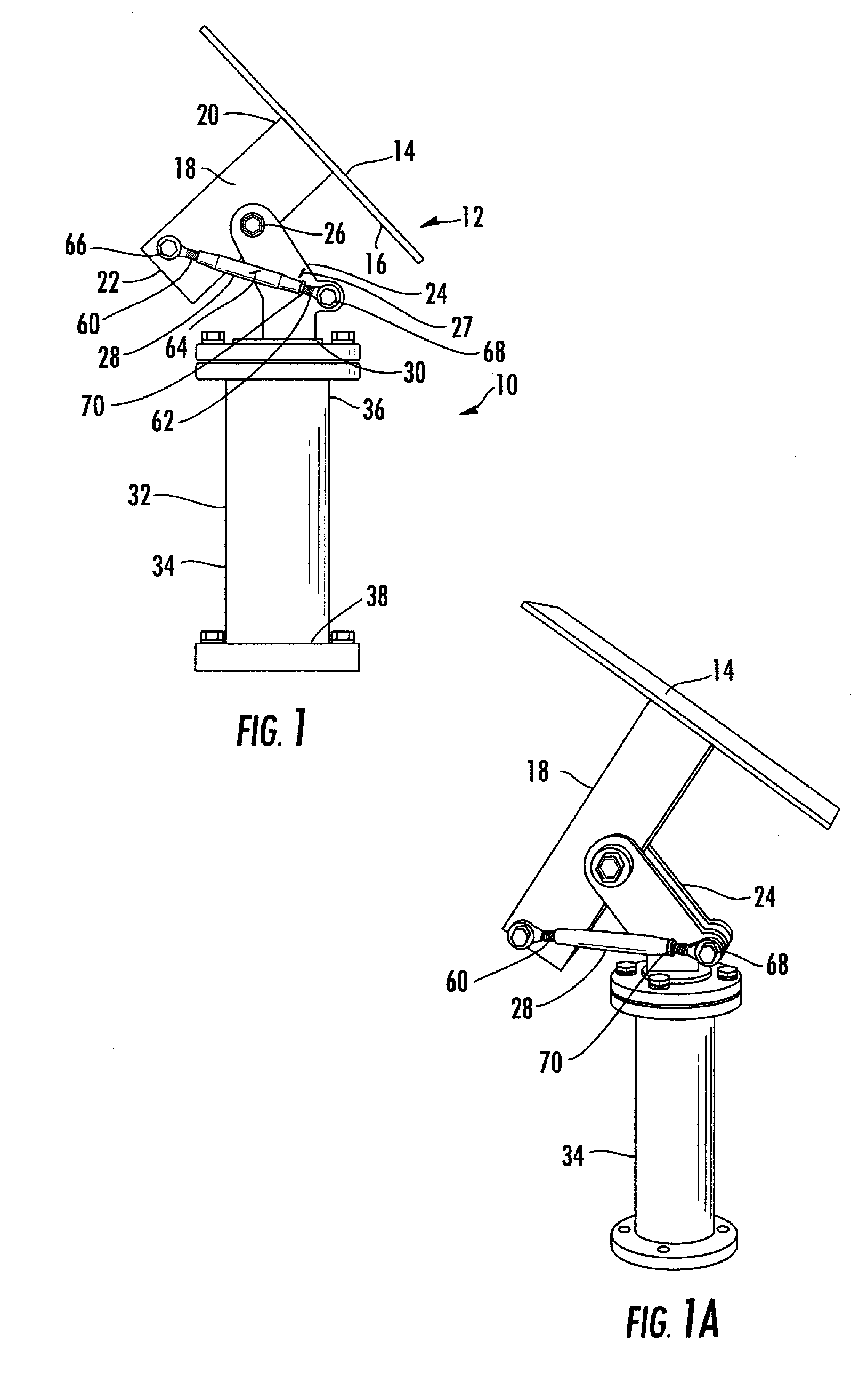
[0024]Referring now to FIGS. 1 and 1a, set forth is a side view of the directional support structure 10 which consists of a mounting plate 12 having a front surface 14 and a rear surface 16. The mounting plate includes mounting apertures, not shown, that can be pre drilled or the mounting plate can be modified for receipt of solar panels, antennas, solar panel basins, and the like type objects that need directional positioning toward a point in space. The mounting plate 12 is coupled...


PUM


Abstract

A directional support structure for use with solar panels, flat satellite antennas, and the like items that are directed toward a point in space. The support structure includes a mounting plate with an extension tube extending outwardly therefrom, pivotally secured to a mounting bracket permitting rotational azimuth alignment of the mounting plate. At least one locking turnbuckle is attached between the extension tube and the mounting bracket to provide locking and vertical adjustable alignment of the mounting plate. The base member includes an attached first flange positioned along an upper end of the base member, an attached flaring positioned on the lower end of the mounting bracket, and an unattached second flange positioned over the flaring, securable to the first flange with fasteners.

Description

FIELD OF THE INVENTION[0001]The present invention relates to a field of support structures and, more particularly, to a support structure for solar panel collectors, satellite antennas and other objects that need to be fixed toward a point in space.BACKGROUND INFORMATION[0002]Solar panels and satellite antennas are directed to a particular point in space to be effective. A solar panel collector must either be directed toward the sun where it will be most effective or made to track the sun as it moves across the sky. Solar panels are used to collect energy from the Sun and require optimum positioning whether the energy is for heating of water or providing electrical power. The weight of the panels is dependant upon the panel size but can be quite heavy if the solar panel includes circulating water.[0003]Satellite antennas, both flat and parabolic, can be found throughout the world for communication purposes. These antennas must also be directed to a particular point in space to be ef...

Claims


Application Information

Patent Timeline
Patent Type & Authority Patents(United States)
IPC IPC(8): A47F5/00A47F7/00F16M11/00F16M13/00
CPCF16M11/10F16M11/12F16M11/2014F24J2/541H01Q1/1264F24J2/523F24J2002/5465Y10T16/53835Y02E10/47Y10T403/645Y10T403/642Y10T403/64Y10T16/5383Y10T403/4688F24S2030/135F24S30/425F24S25/10F16B2200/50F16B2200/406F16B2200/503F16B2200/506
Inventor STANEY, WAYNE
Owner STANEY WAYNE
Why Eureka
Try Eureka